In my last post I’ve introduced a proof-of-concept Arduino solar charger shield. I went through the hardware as well as the way it works - or at least is intended to work. It was prominently linked on dangerousprototypes.com as well as some other sites and got quite a bit of publicity as a result. Thank you all for sharing this post.
By the way: here’s an overview over all posts on this project.
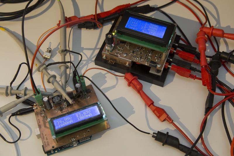
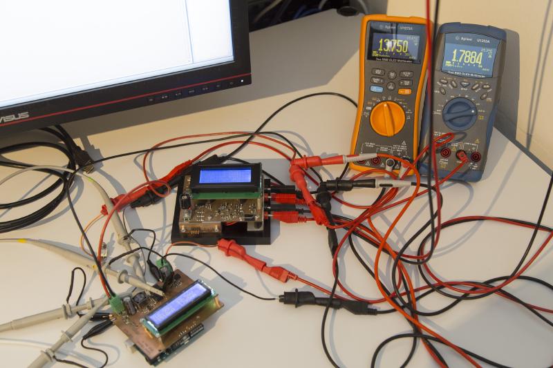
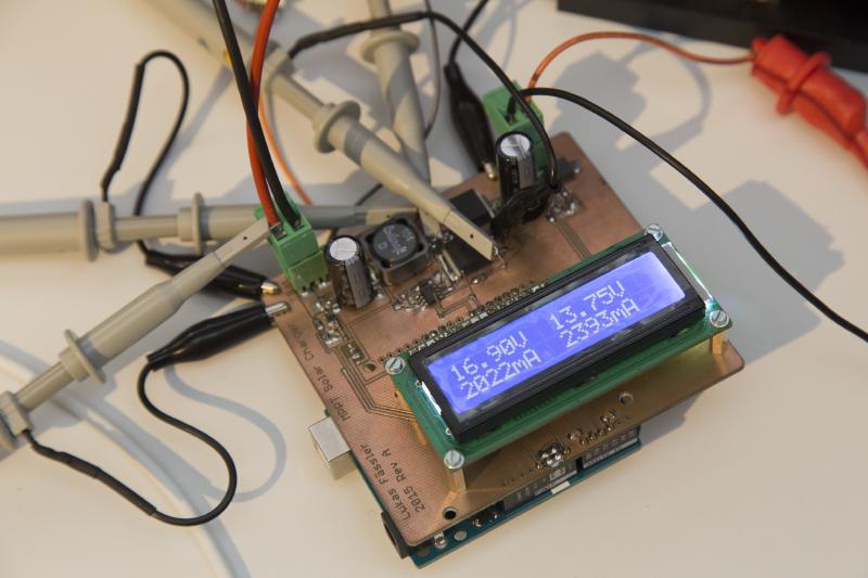
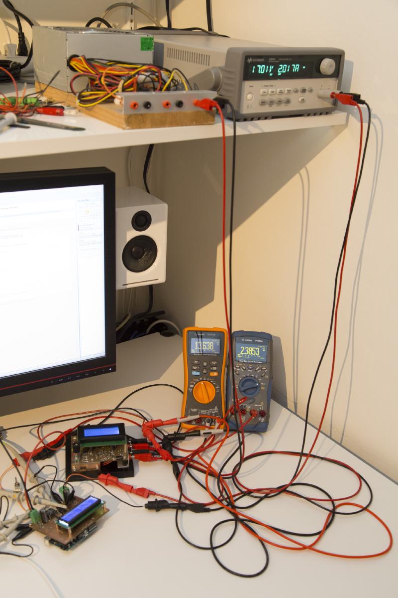
This time I’ll show you some results of the testing that I’ve done. The basic test setup is shown above: The solar charger is hooked up to my home-brew constant current dummy load, together with a pair of DMMs at the output in order to precisely monitor output voltage and current. For the input I’m relying on the lab supply to provide these measurements. And yes, the shield does its own measurements of both input and output currents and voltages. Once calibrated they are even quite accurate but I won’t rely on them for things as calculating the converter’s efficiency.
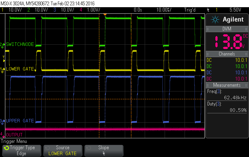
But first we need to see if our converter works at all. As the scope screenshot above demonstrates - it does. For all the tests shown in this post, the input voltage was provided by a lab supply set to 17 volts. So we’re not yet testing the software and its capability to draw just the right amount of current.
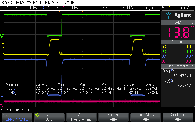
As you can see, since the converter can draw any (reasonable) current at the input, it provides the maximum voltage (set in software) of 13.8V at its output. In order to do that, the upper FET is on approximately 80% of the time. The signals all seem nice an clean and there is no noticable ripple at the output at 1V/div and no load. And the switching frequency is 62.5kHz (16MHz / 256) as expected.
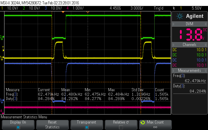
At 1 Amp output current, the software has to increase the duty cycle somewhat to 82% (above) and even further to 84% at 2A (below). Besides that, everything still looks very similar under load conditions.
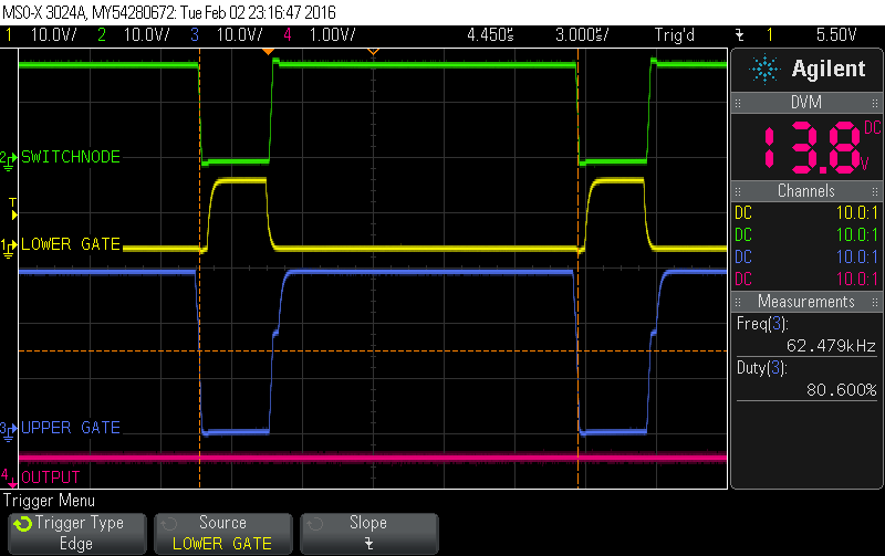
In my last post I’ve raised the question if the FET driver’s dead time of 540ns according to the datasheet is not a bit excessive. Well, let’s look at the dead time on the scope. First of all we can observe that the dead time of the IR2104 is in line with the data sheet. I don’t have it in front of me right now to check the min/max specs but the measured 522ns seem reasonably close to the theoretical 540ns.
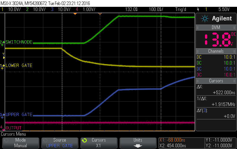
From looking at the screen shot above, the dead time does seem a bit long. The reason dead time is introduced is to prevent shoot-through. If both FETs are on there is a short-circuit from the input to ground. Together with the input capacity and the FETs low Rds-on, very large currents could flow, possibly destroying the FETs and at least detoriating efficiency. So introducing a bit of time when both transistors are off seems reasonable. But too much of it also costs efficiency since current has to flow through the diode instead of the lower FET. The main reason for using a synchronous topology is to prevent this in order to gain efficiency. So obviously one has to find a balance. I think here we’re a bit far on the conservative side but never mind for now.
So now that our converter is working, let’s take a look at efficiency. I’ve measured the efficiency at output currents ranging from 100mA to 2.6A in 100mA steps with the input voltage at 17V. I didn’t use the sense-wires connections on the lab supply so I had to compensate for the voltage drop on the input leads manually.
The results are quite impressive:
- 95.5% @ 100mA (worst)
- 96.9% @ 200mA
- 97.9% @ 400mA
- 98.1% @ 800mA (best)
- 97.1% @ 1600mA
- 95.7% at 2600mA
So the efficiency is constantly at a very high 95.5% and better over the entire current range of interest.
The resulting loss is less than 1.6 Watts @ 2.6A out. As a result, the shield never gets hot, even when running at this power level for a while.
Note that this is quite a bit more power than the converter was designed for. 37W as opposed to the 30W I designed it for. The FETs could even handle much more. The limiting factor would likely be the coil reaching saturation. Unfortunately my lab supply doesn’t supply any more than 2.2A so I can’t push it any further.
One thing to note is that these efficiency figures don’t take into account the power consumed by the arduino, the display, the fet driver, current monitoring ICs and so on. This brings us to the last topic for now: The current consumed by the various components. I did these measurements mainly in order to understand how to limit power consumption in a later version. To me, this shield is only a proof of concept and so reducing power consumption was never an issue.
Here are the results:
- Arduino: 48.7mA
- LCD backlight: 8.9mA
- LCD excluding backlight: 1.148mA
- FET driver (standby): 106.56uA
- FET driver (62.5kHz, Iout=0): 2847uA
- FET driver (62.5kHz, Iout=2.5A): 2937uA
- Current sensors (each): 48.6uA
So the arduino itself is using up the lion’s share of current. Next comes the LCD backlight. Nothing unexpected so far. The LCD without backlight still consumes a considerable 1.15mA, no matter if it’s on or off. The FET driver uses around 2.9mA when on and only about 0.1mA when off. Output current only has a minor impact. The current sensors don’t use up much - less than 0.1mA for both.
Check out my next post for a closer look at the software or here for an overview over this project.