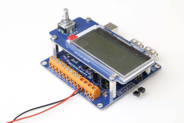
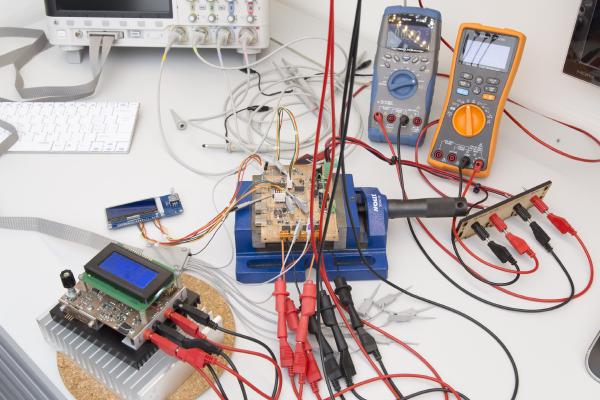
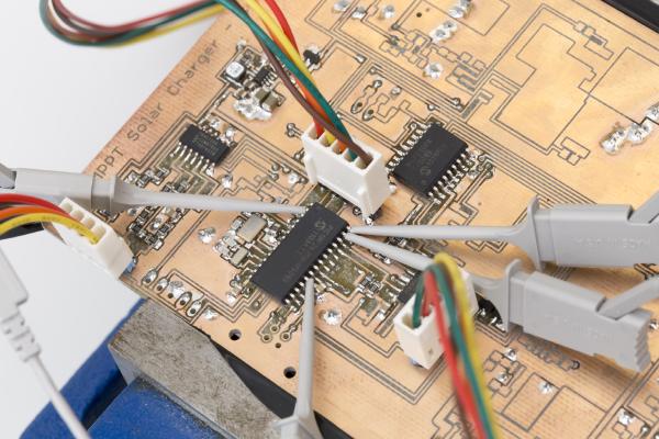
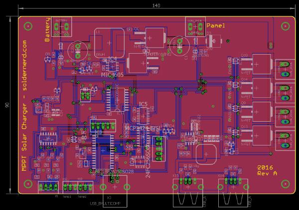
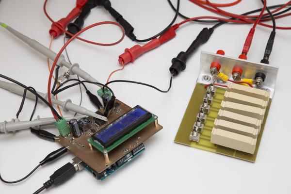
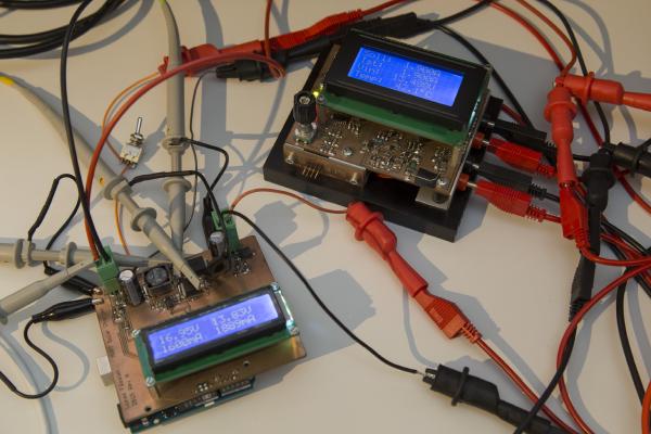
Over the last few weeks I have been quite busy with my MPPT Solar Charger project. I’ve built up a first board and started writing firmware for it. Since the last version was not too different in terms of hardware I was able to re-use most of that code. But I hadn’t even touched on the whole USB stuff back then so there was still a lot of work to do. While the project is still far from being complete I am happy to say that I’ve made quite some progress. Most importantly, the new design seems to work well and so far I haven’t found any mistakes in the board layout. But let’s go through this step by step.
It’s time to follow up on the MPPT Solar Charger project. Progress has been slow since I’m currently working full time and doing a master’s degree at the same time. Given that this blog has previously been something close to a 50% job at times things will necessarily slow down a bit. But all the projects, including this one and the ultrasonic anemometer are alive and well and I’m working on them whenever I find some time.
In a previous post I have presented a design for an MPPT Solar Charger. In the mean time I have built a prototype and also wrote some software for it. So today I’ll go through my findings of what works well and what needs to be improved. And yes, there are some flaws in the design…
I’m currently waiting for the boards for my Ultrasonic Anemometer Rev B to arrive from Hong Kong and this gives me some time to write about the MPPT Solar Charger design that I did quite some time ago. I published a series of posts on a Arduino MPPT Solar Charger Shield and got a lot of encouraging feedback. But that shield was more of a proof-of-concept than a finished product. While it generally performed well it drew way too much current when idle to actually be deployed unless you can count on plenty of sunshine every day.
There have been two previous posts on this project: one on the concept and the hardware and one on hardware testing. You probably want to check them out first if you’re not yet familiar with this project. Or even better: Click here for an overview over this project.
First tests are being performed on the Solar Charger Shield In my last post I’ve introduced a proof-of-concept Arduino solar charger shield. I went through the hardware as well as the way it works - or at least is intended to work. It was prominently linked on dangerousprototypes.com as well as some other sites and got quite a bit of publicity as a result. Thank you all for sharing this post.
A friend has approached me regarding his solar project. He wants to install a solar panel together with a battery and an inverter in order to have power at his allotment garden. He had looked at a hobbyist project where an arduino was used to build a MPPT (maximum point of power tracking) charge controller. I took a look at the design, liked a lot of what I saw and decided to build something similar.