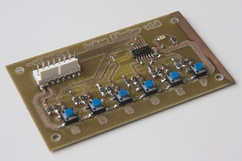
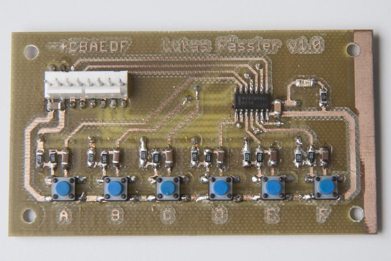
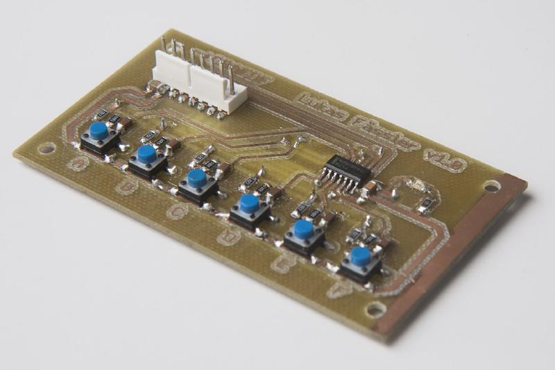
This was one of the first PCBs I ever made myself as well my very first attempt at soldering SMD components. So if you were wondering why some of the copper on the right has not been removed - that’s why. At that time, I was not even using Eagle yet but some software called Sprint Layout. But this post is not really about this unimpressing board but about proper debouncing. Something I feel strongly about ;-)
As opposed to many people out there, I still prefer to do all my debouncing in hardware. Yes, of course you can do debouncing in software and sometimes you may have to but if you have a choice, debouncing in hardware will generally yield better results and reduces software complexity. Most of the time, my switches will directly trigger an interrupt on a microcontroller so you really want to avoid false triggering. All that context switching associated with an interrupt adds quite some overhead compared with just reading an input pin so there are performance implications of this as well.
Jack Ganssle has written a really nice paper on this. It can be found here: http://www.eng.utah.edu/~cs5780/debouncing.pdf. He has run some experiments with a wide variety of switches and explains how to deal with them in practice. What I was doing here follows the recommended approach from Jack’s paper: You take a switch and a pull-up resistor, run the resulting signal through an RC filter and add a schmitt-triggered buffer. Cheap, simple and works perfectly every time.
Here are the signals you get when the button is pressed (top) or released (bottom). Yellow is the output of the RC filter and red is the (digital) output of the schmitt-triggered buffer. Note that the 74HC14 is an inverting buffer so the output signal goes from low to high when the button is pressed.


The time constant of the RC filter and therefore the resistor and capacitor values are quite uncritical if you are working with simple switches as here. As you can see in the scope screens above, it takes around 20ms from when the button is pressed (or released) until the output signal changes. That’s more than enough time even for a pretty poor switch to have stopped bouncing. At the same time, that’s instantaneously as far as the user is concerned. Anything up to 50ms feels instantaneous even to impatient humans.That leaves 30ms for the microcontroller to take the desired action. If that’s enough depends of course on what you are trying to do but generally that’s plenty of time.
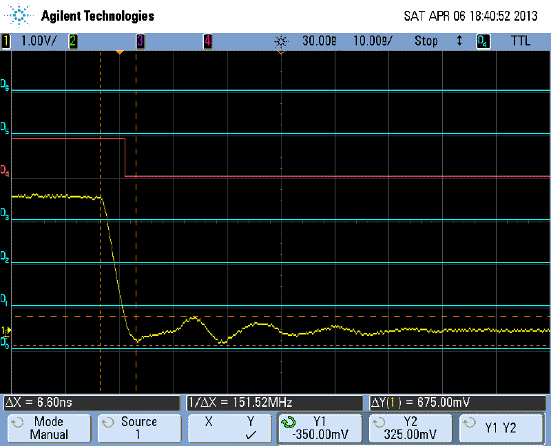
Here’s yet another screenshot. This time it’s the digital output (red) as well as the same signal in analog. This is just to convince you that what your are getting is really a clean output signal. It goes high to low in less than 10ns. That’s less than one-sixth of a clock cycle on a typical (16MHz) microcontroller. Yes, there is some ringing but there always is if you look closely enough. In this case it’s well behaved with less than 700mV pp amplitude and dies out within 50ns or so.
Getting the balance just right gets much trickier when you’re using rotary encoders. You won’t press a pushbutton 100 times a second but it’s not uncommon to get signals from an encoder with only a few milliseconds between them. So you have to think carefully about how much debouncing you need. Just a bit too little and you pick up bouncing noise. A bit too much and you start missing pulses.
I’ll share my lessons learned on that, too. But that’s for another post in the future.
Here you find the Eagle files as well as PDFs of the board and schematic as a zip file (file no longer available).