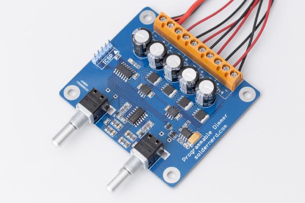
Around one and a half years ago I’ve designed and built various LED dimmers for both white and RGB LEDs. Then late last year someone approached me asking if I could make an RGB dimmer for him, too. But my designs were really tailored to their specific applications and built with home-made, i.e. milled PCBs which are time-consuming to make. So I decided to make a more universal version based on a proper, etched board which could be built in a small series and used for all kind of applications, both white and RGB. The result is this versatile, programmable 4-channel dimmer.
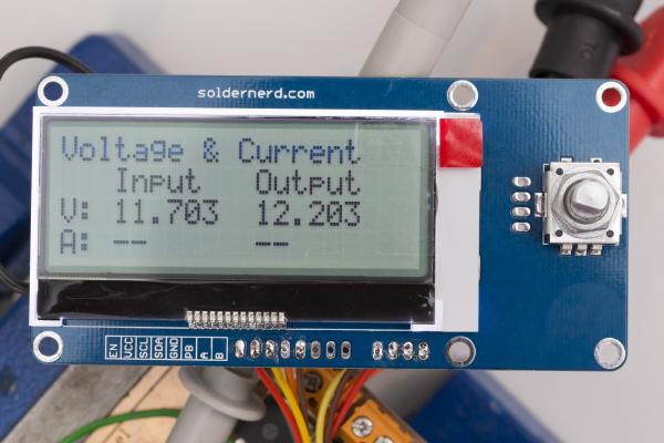
As you may have noticed I’m quite busy working on the MPPT Solar Charger project. The latest version uses a 4 lines x 20 characters LCD that connects via I2C as well as a rotary encoder with a push button.
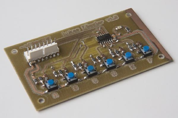
Finished RGB dimmer In my last post I’ve described the design and construction of my LED dimmer project. This project here is similar but a bit more involved. It controls RGB LEDs so it can not only change the brightness but also the color of the light. Instead of a simple pot it used a pair of rotary encoders with push buttons. One controls the brightness, pushing its button turns the light on or off. The other changes the color, pushing its button toggles between color and white.
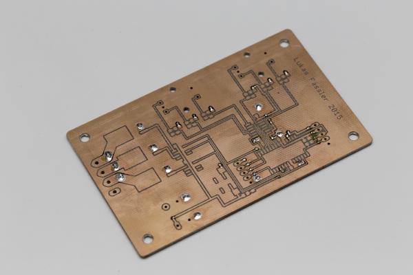
This was one of the first PCBs I ever made myself as well my very first attempt at soldering SMD components. So if you were wondering why some of the copper on the right has not been removed - that’s why. At that time, I was not even using Eagle yet but some software called Sprint Layout. But this post is not really about this unimpressing board but about proper debouncing. Something I feel strongly about ;-)