Some of you may have seen my arduino-based inductance meter in this post: https://soldernerd.com/2014/12/14/arduino-based-inductance-meter/. The guys at dangerousprototypes.com picked it up (http://dangerousprototypes.com/2014/12/16/arduino-based-inductance-meter/) and this blog got more visitors than I could ever have imagined. Thanks, dangerousprototypes.
The arduino-based meter works well and made a great proof-of-concept. But for everyday use you’re probabely not looking for an arduino solution but rather something that looks and feels more like a multimeter. That’s why I’m following up with this stand-alone version.
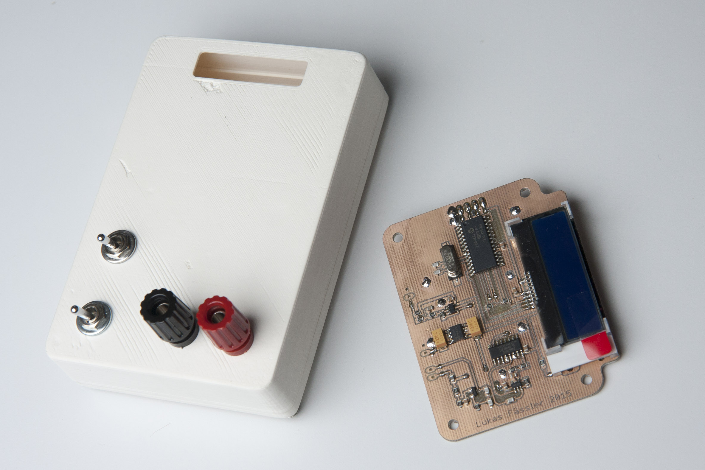
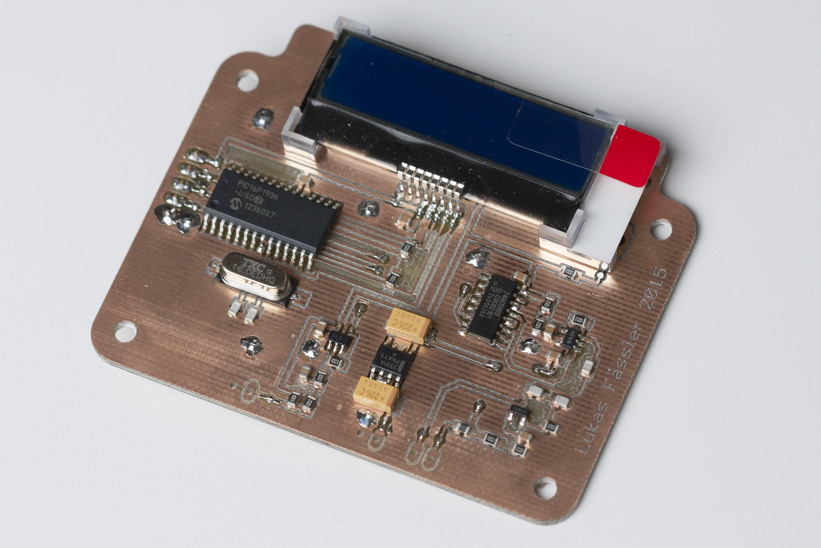
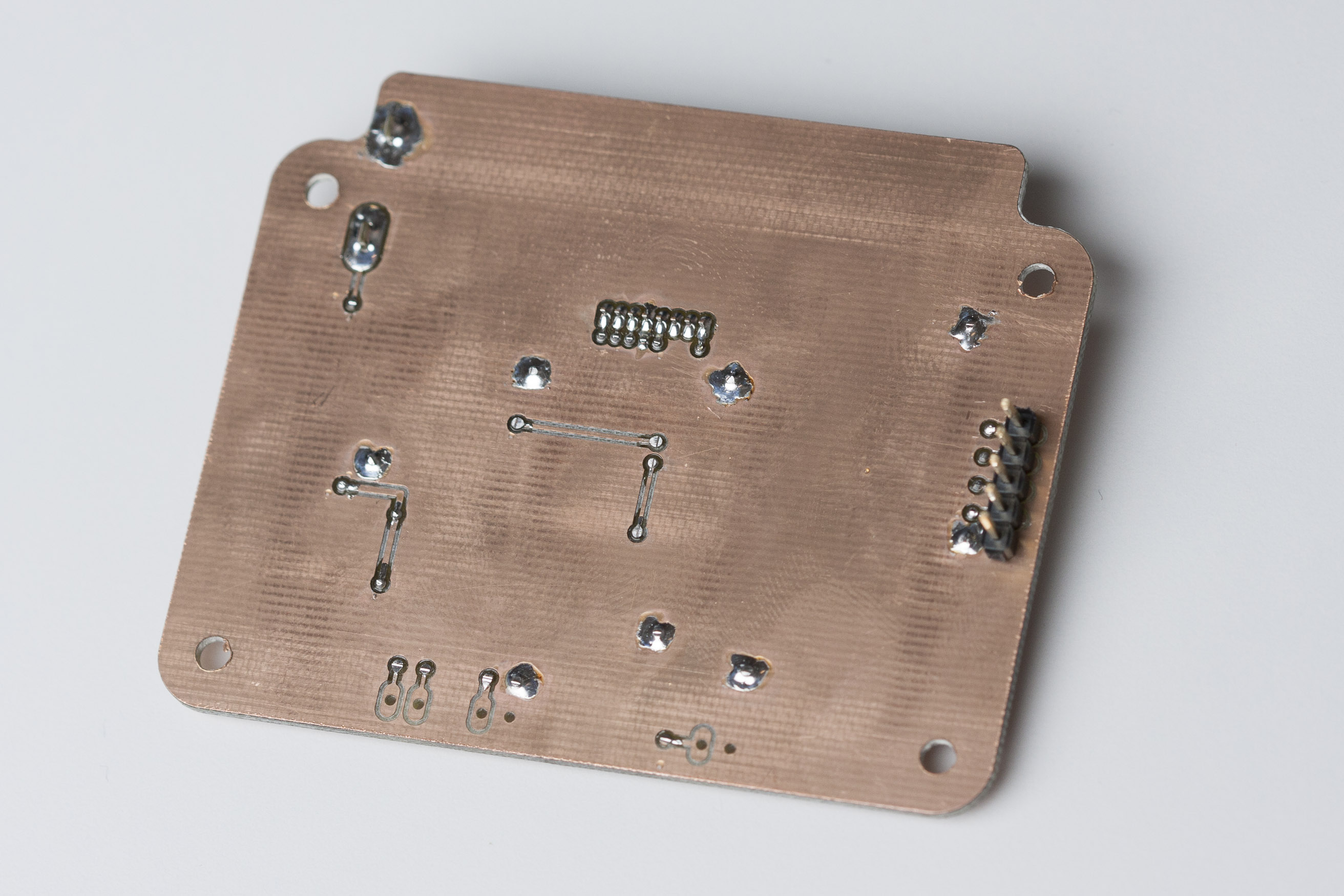
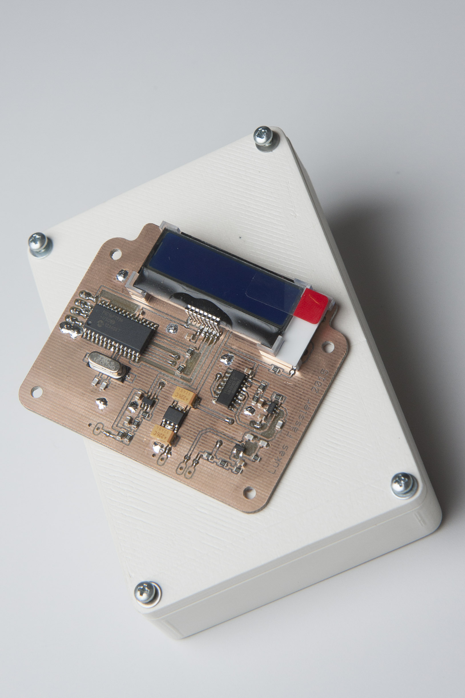
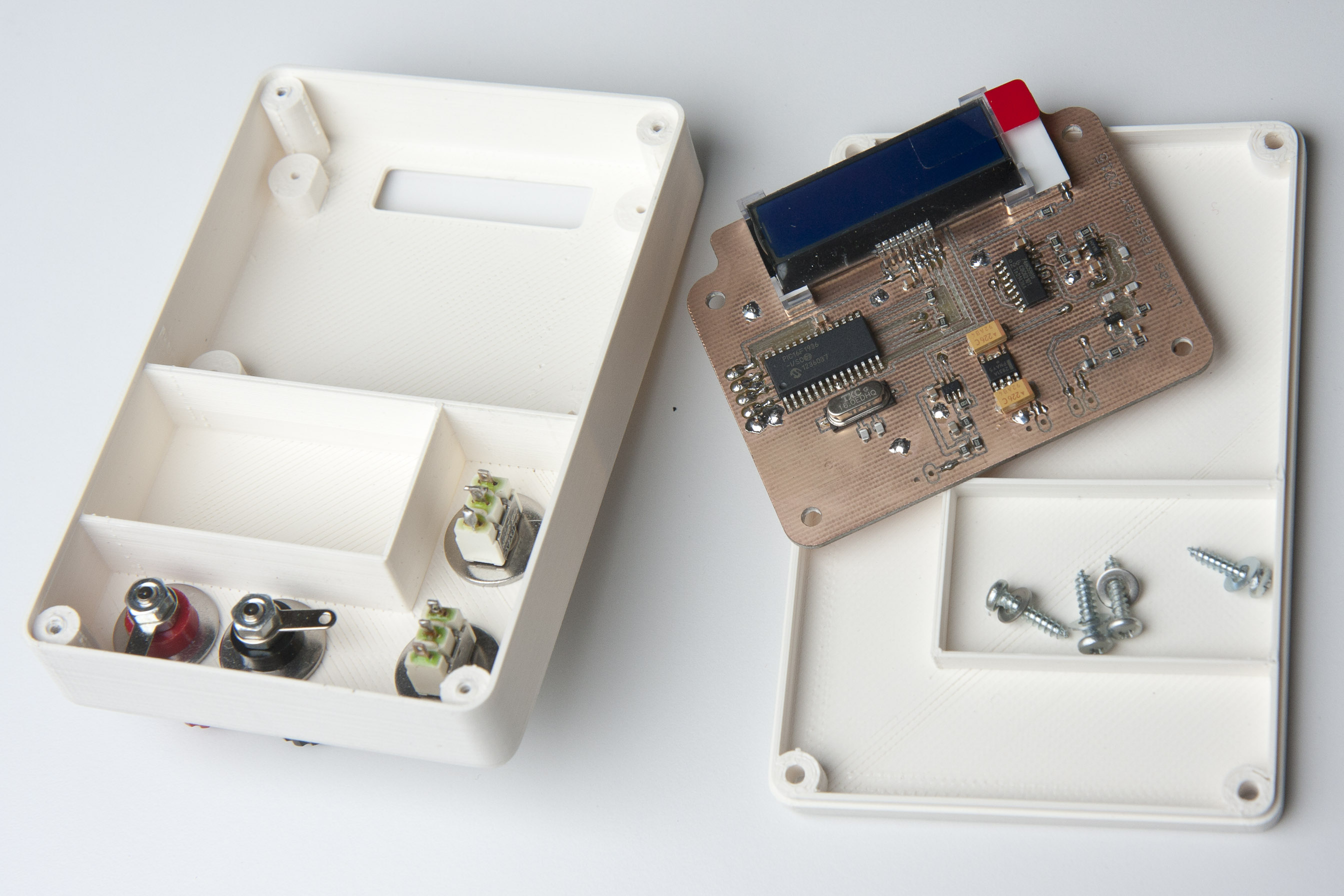
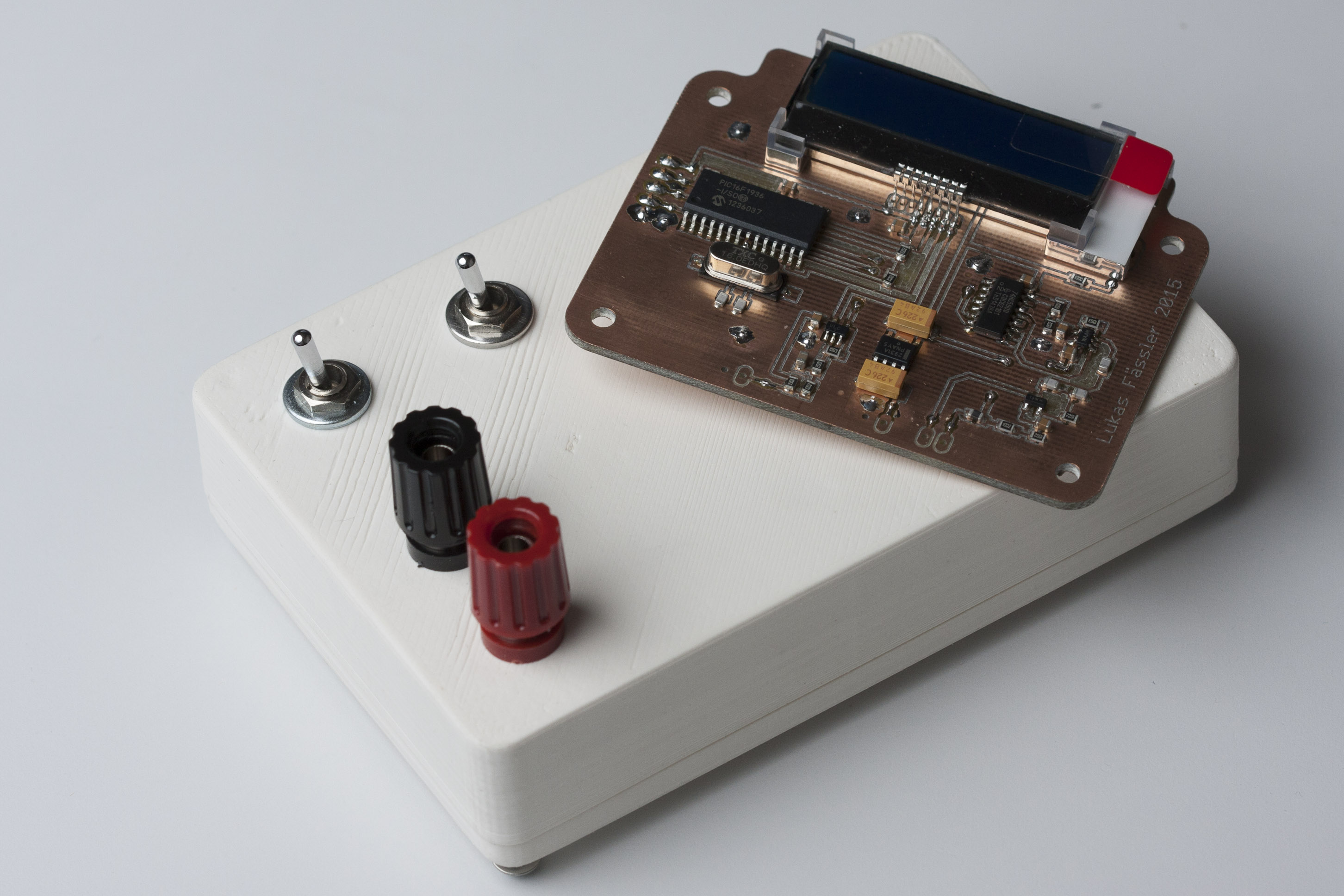
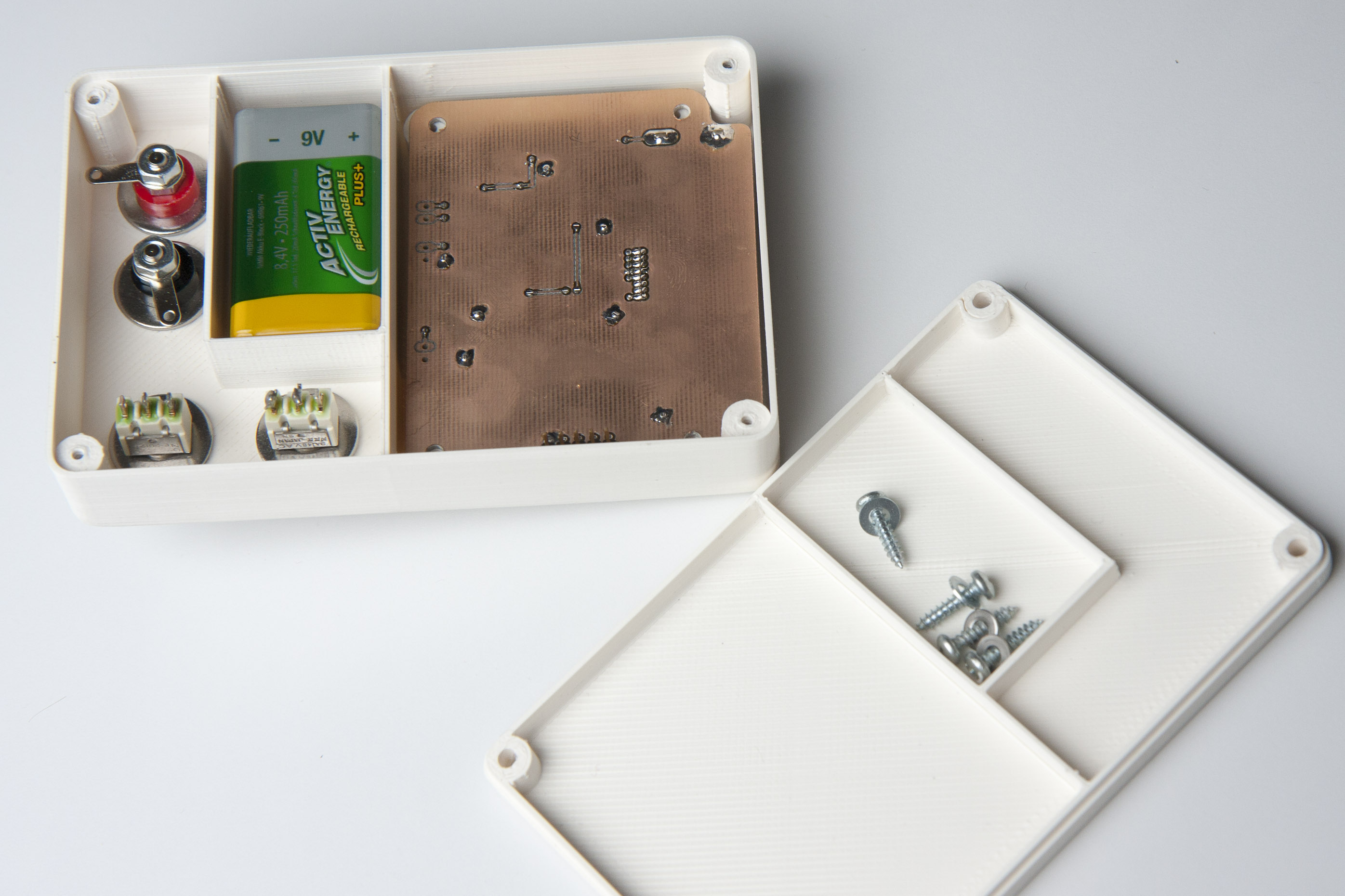
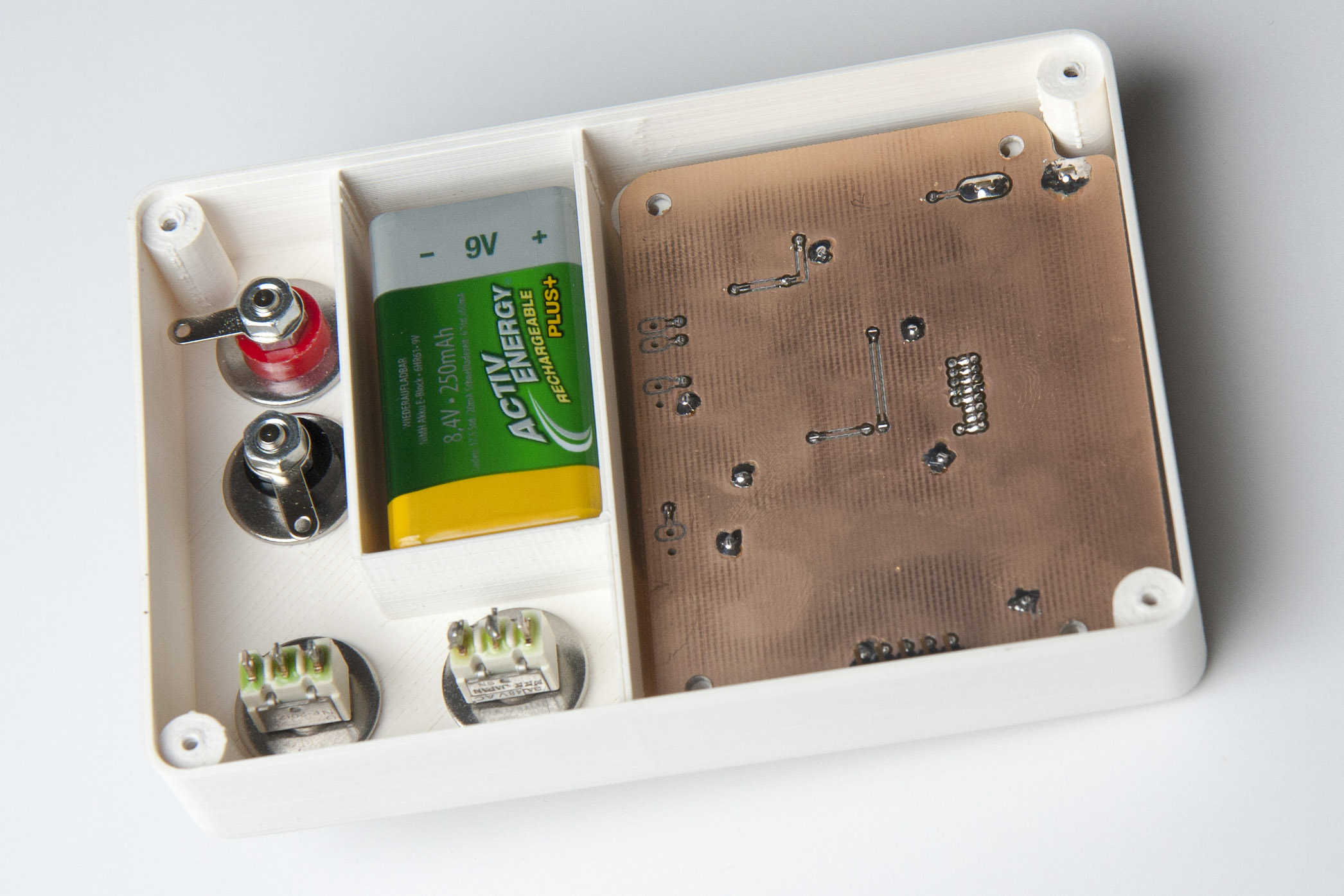
So this version is battery powered and comes complete with a 3D-printed case. It uses a mid-range PIC microcontroller, a PIC16F1936. Not that there’s much special about this model, I just happened to have some left from previous projects. I also thought about using a Atmel Atmega328, the same chip that is on the Arduino UNO.
Using an entirely different chip means I’ll have to write the software from scratch. But I felt that the Atmega328 was just too much of an overkill just to measure a frequency and control an LCD. They are quite a bit more expensive than the PIC, CHF 3.70 compared to CHF 1.90 @10pieces at Farnell where I get just about all my chips.
Talking of the LCD: The one I’m using here comes with a I2C interface. It’s blue with a white backlight and 2×16 characters and really tiny. I bought 2 of them years ago because they were small and relatively cheap (around 15CHF) and don’t require so many precious I/O pins of your microcontroller. Somehow I never used them but here their small size makes them a good choice. I/O pins aren’t a constraint here obviously as most of the 28 pins are unused.
I’m not yet familiar with the details of how they are controlled. I had a look at the data sheet and it looks like you send them just about the same commands like with the standard Hitachi compatible ones, just over I2C. But I expect to spend an evening or two figuring out the details.
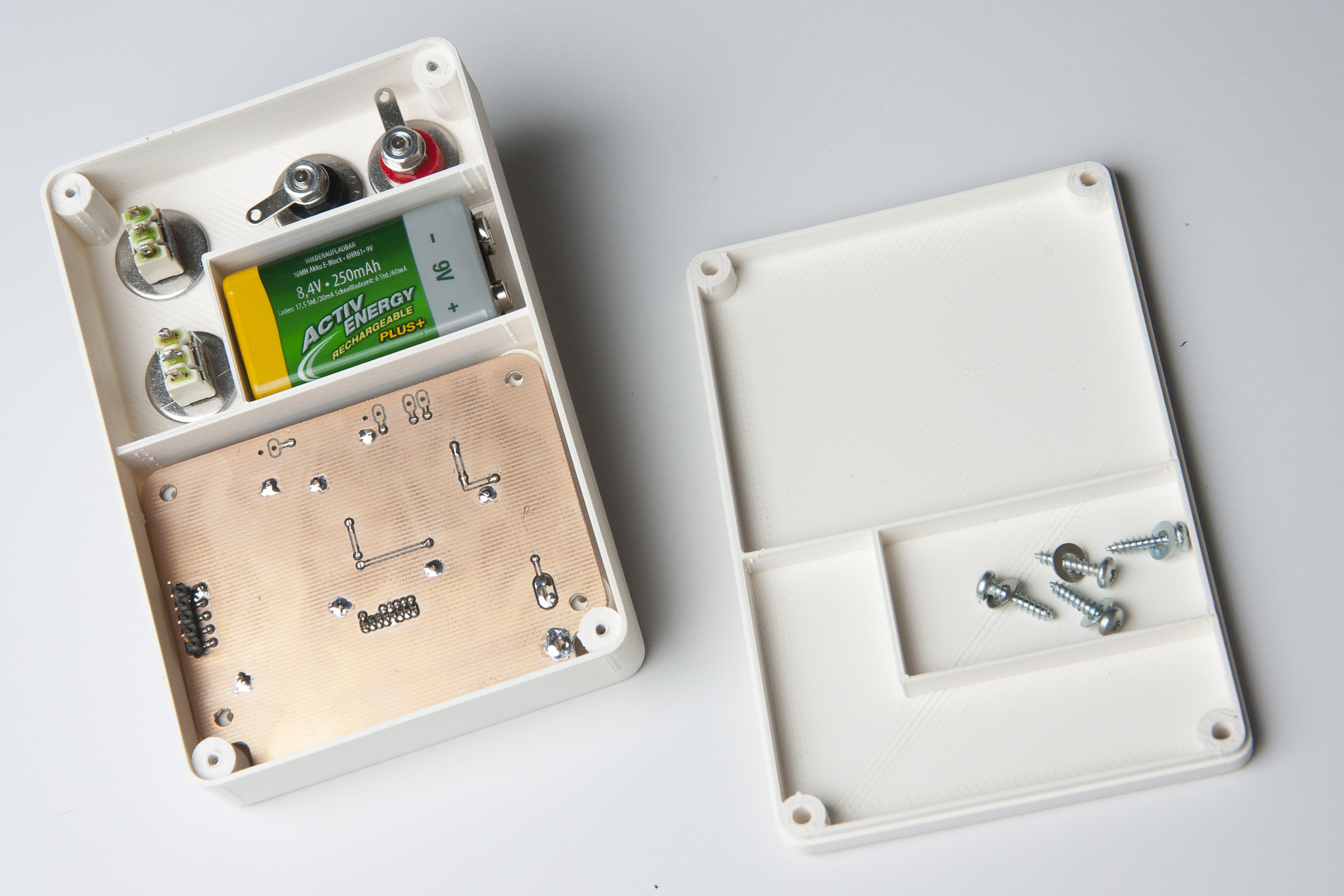
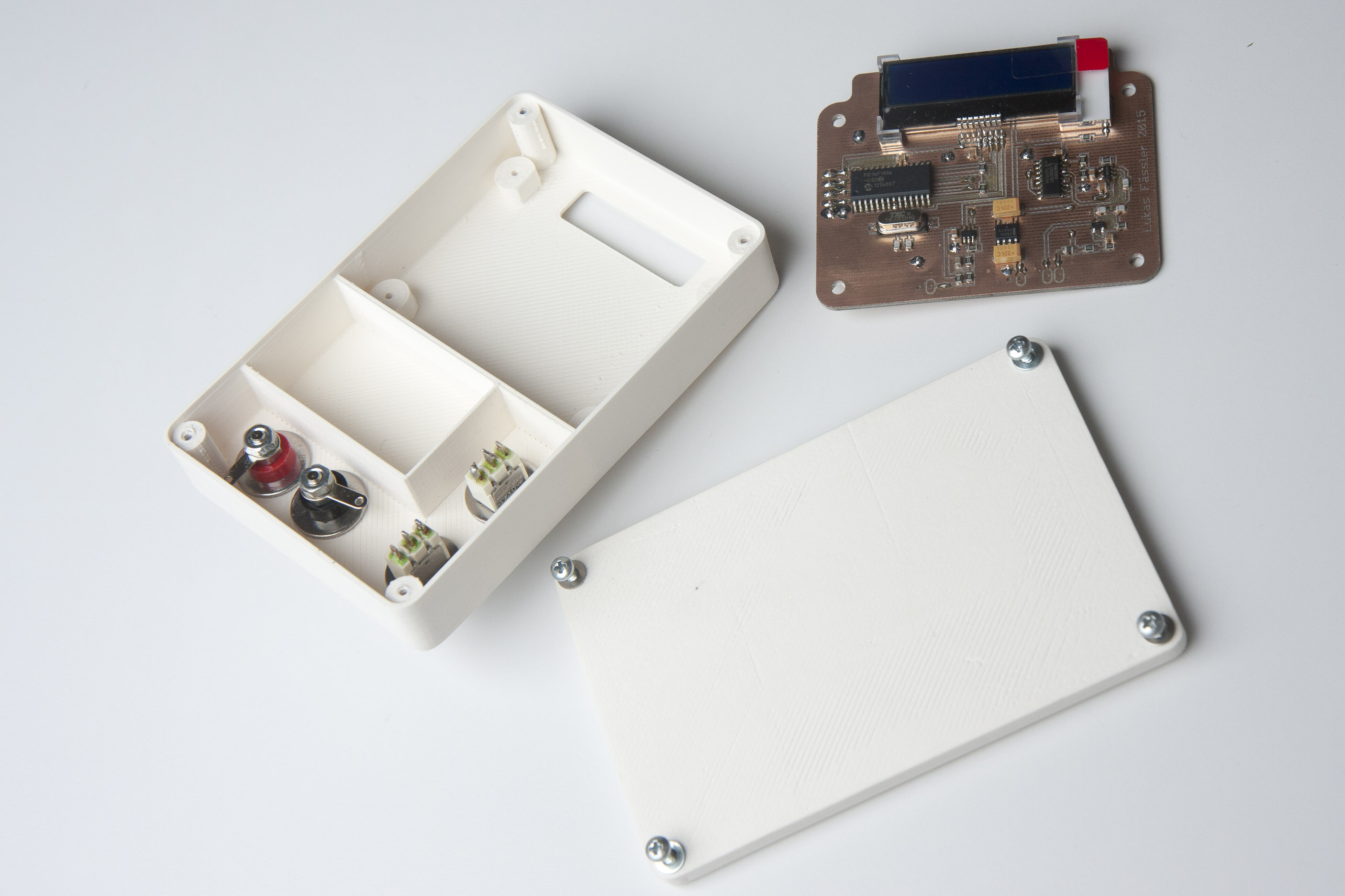
The case was designed using FreeCAD. As the name suggest, it’s a free (and open-source) CAD design tool. This was only the second time I was using it but I found it quite easy to learn.
I printed the case at the Zürich fab lab (zurich.fablab.ch) on one of their Ultimakers. Was my first 3D-printing project, thank you very much for your support, everyone.
As always, I’ll put all the files online as a zip. So you can download all the Eagles plus PDFs as well as the FreeCAD models. Here it is: InductanceMeter. I haven’t written any software yet but I’ll but that online, too, as soon as it’s finished.
The software is ready now. Klick here for the next post: https://soldernerd.com/2015/01/23/stand-alone-incuctance-meter-finished/.

Hello Lukas!
What do You think – or did You already check it – what is the upper limit in measurement of this oscillating circuit, what is the largest inductance that can be measured with it safely?
We have a small project: we would like to measure the position of hydraulic trim tabs of a boat that has single coils inside as position feedback. We checked, and its range is ~30-250 mH (milli, not micro).
Best regards,
Peter
Hi Peter
I don’t have a coil near as large to try it myself. The largest values I’ve measured was 1mH. So the question really is if the circuit will oscillate with such a large inductance but I don’t see any reason why it shouldn’t. If it oscillates everything will work fine. I just did the math and the resonant frequency would be in the range of 14 to 41kHz which is then divided by 256 to be measured. That’s a totally acceptable value from the software’s point of view so I wouldn’t expect any problems.
Thanks for the answer!
And what do You think, is there any special reason to use the BFR92A, or a simple 2N3904 should be enough for such a low freq? And why did You include L1 1uH in the schematic, is it a reference value or a short circuit protection?
The choice of the transistor should not be critical at all. The BFR92A was just something that I had on stock. The 1uH inductor serves two purposes: it limits the maximum resonant frequency to something the PIC can handle. and it allows you to zero the meter by short-circuiting the test leads since L1 lets it resonate.
Could it be modified to pick up a hidden coil that was tuned to between 120-150 kHz?
Please, tell me – can it work with LCD based on ST7032 controller, like this
https://aliexpress.com/item/32807890814.html