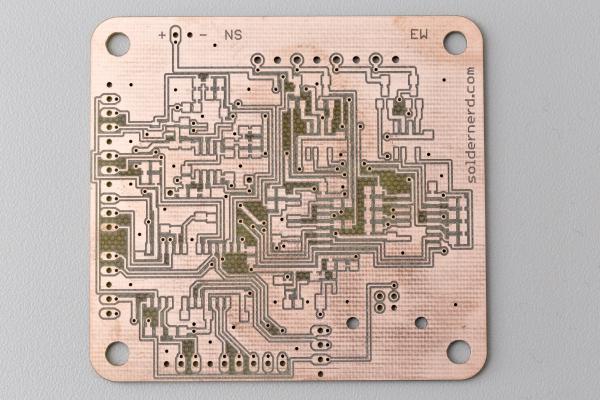
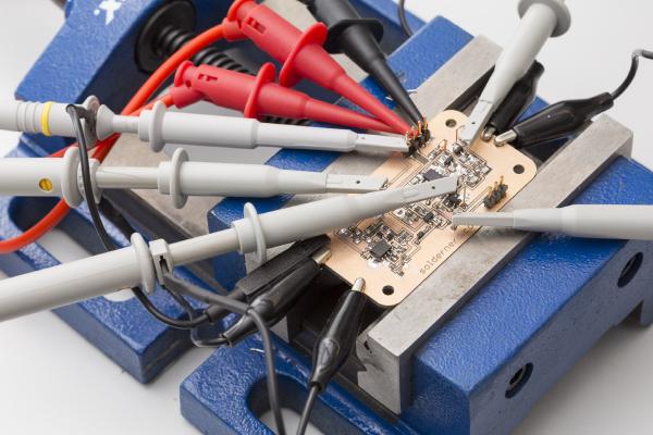
I last time proudly presented the new RevB board and got a lot of feedback from people who want one, too. As mentioned I have all the components here to ship up to 10 kits but I was reluctant to send anything until I had the chance to do some hardware testing. Not much had changed since the last revision but I don’t like taking chances on things like this.
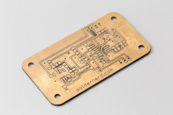
Good news: the boards from dirtypcbs.com have arrived and look great. I also got all the components for the 11 boards. Why 11? I ordered about 10 (they call it a protopack) and was lucky enough to get 11. Thats dirtypcbs.
I recently ordered my first PCB at dirtypcbs.com and the result was promising. So there was nothing stopping me from finalizing the Rev B of my standalone Ultrasonic Anemometer and ordering a protopack. I’ve placed the order a few days ago and expect the boards to arrive here in 2 to 3 weeks. This should be good news for all those of you who have been asking for kits and want to contribute to the further developement of this project. I’ll build up one or two boards as soon as they get here and do some testing. If everything works as planned I can order some more components and ship some kits soon after that.
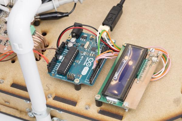
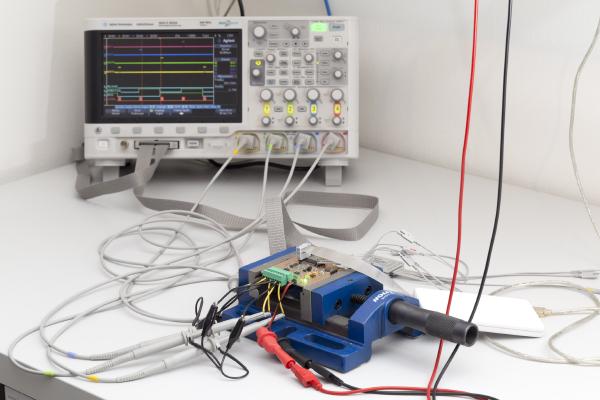
It’s been a long six weeks since my last post but that doesn’t mean that I haven’t done anything since. Among other things, I wrote some code to get the I2C interface working and hooked the anemometer up to an Arduino Uno with an LCD display attached. Apart from demonstrating the I2C interface this also nice for testing. For the first time I can see what this thing is measuring in real time without hooking it up to a PC over USB.
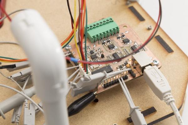
In my last post I was happy to report that I managed to get the USB interface to work. This interface has since proved to be extremely valuable in software development and testing. While the device is taking measurements you can look at the results (or intermediate results) at your PC in real time. You can even log large amounts of data to a .csv file and inspect the results in Excel.
Last time I outlined my reasons to ‘go digital’ by adding a powerful on-board microcontroller and designing a standalone wind meter.
In the weeks that followed that decision I tried to find a suitable microcontroller and to design a prototype. Today I’ll show you the result of that work.
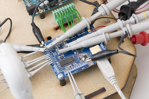
In my last post I went through the design of the analog part of the ultrasonic anemometer. Today we will see how the circuit designed last time performs in practice.
Recently, I’ve sucessfully tested the new driver ciruit for my ultrasonic anemometer. It performed even better than I expected and I will be happy to use it pretty much as it is.
In my last two posts I have gone through my new anemometer circuit both in theory and practice. Click here for an overview over my ultrasonic anemometer project.
Last time I’ve presented my new design for the ultrasonic anemometer driver circuit. So now it’s time to see how it performs. If you’re new to this project you might want to check out the overview page or at least my last post.