It’s time to follow up on the MPPT Solar Charger project. Progress has been slow since I’m currently working full time and doing a master’s degree at the same time. Given that this blog has previously been something close to a 50% job at times things will necessarily slow down a bit. But all the projects, including this one and the ultrasonic anemometer are alive and well and I’m working on them whenever I find some time.
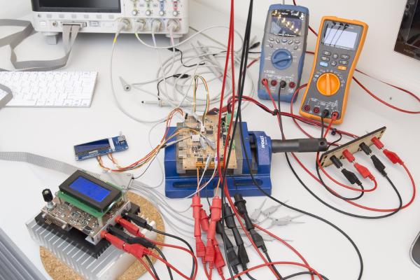
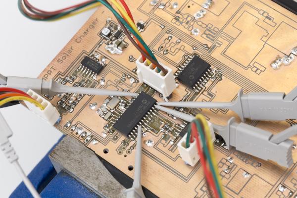
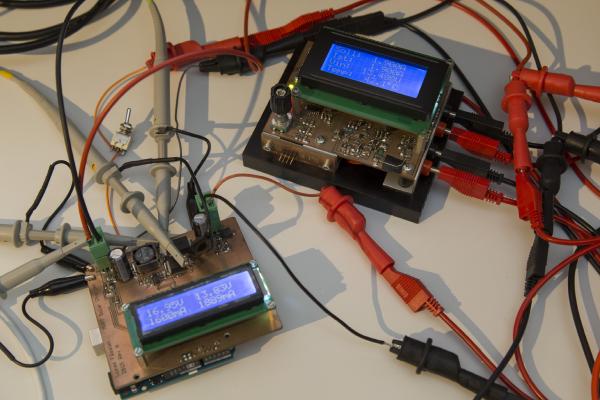
In a previous post I have presented a design for an MPPT Solar Charger. In the mean time I have built a prototype and also wrote some software for it. So today I’ll go through my findings of what works well and what needs to be improved. And yes, there are some flaws in the design…
I last time proudly presented the new RevB board and got a lot of feedback from people who want one, too. As mentioned I have all the components here to ship up to 10 kits but I was reluctant to send anything until I had the chance to do some hardware testing. Not much had changed since the last revision but I don’t like taking chances on things like this.
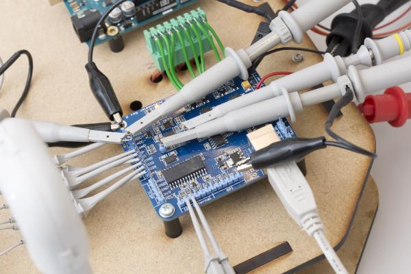
First tests are being performed on the Solar Charger Shield In my last post I’ve introduced a proof-of-concept Arduino solar charger shield. I went through the hardware as well as the way it works - or at least is intended to work. It was prominently linked on dangerousprototypes.com as well as some other sites and got quite a bit of publicity as a result. Thank you all for sharing this post.
It’s been a while since I posted the last update on the anemometer project. The reason for this is that I’m struggling with the aerodynamical design.
By the way: Click here for an overview over the ultrasonic anemometer project: /projects/arduino-ultrasonic-anemometer/