Have you ever tried to write a program that connects to some device via USB? I have done so a few years ago and was shocked how much of a pain that is (at least on a Windows plattform). I always thought there should be a nice little library that wraps all those uggly DLL imports, marshalling and COM API calls and offers a nice and clean C# interface to the outside world.
It’s been almost three weeks since my last post and some further progress has been made. I’ve upgraded the microcontroller and can now control the gain of the second amplifier stage in software. But let’s look at the changes in some more detail.
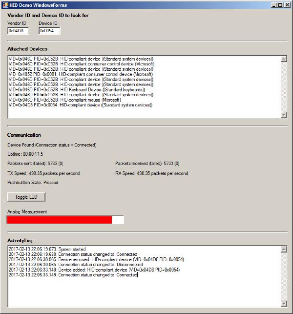
In my last post I was happy to report that I managed to get the USB interface to work. This interface has since proved to be extremely valuable in software development and testing. While the device is taking measurements you can look at the results (or intermediate results) at your PC in real time. You can even log large amounts of data to a .csv file and inspect the results in Excel.
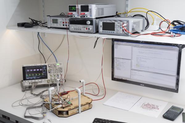
Last time I went through the design of my new standalone anemometer. Now it’s time to build this thing and see if it works as planned.
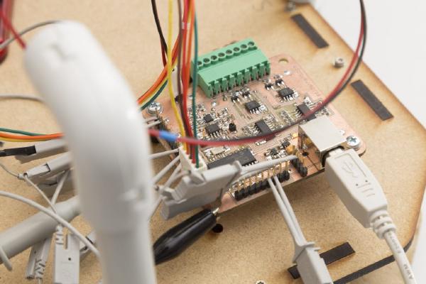
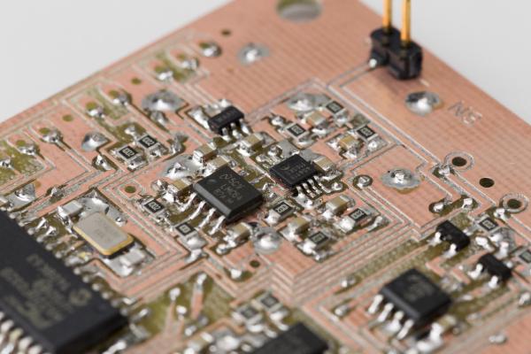
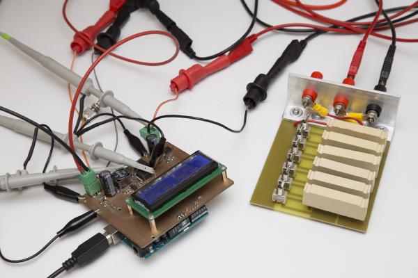
After I fried a couple of chips on my driver circuit testing board due to a wrong chip in the power supply I was a bit more careful this time and built up the board step by step.
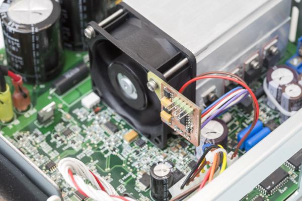
I’m currently mainly working on my new anemometer design but once in a while I get distracted. For example when my Keysight E3645A lab power supply was making so much noise that I could hardly concentrate. That’s when the idea of this fan controller was born.
There have been two previous posts on this project: one on the concept and the hardware and one on hardware testing. You probably want to check them out first if you’re not yet familiar with this project. Or even better: Click here for an overview over this project.
If you’ve read my last post you’re already familiar with my Inductance Meter project: /posts/stand-alone-inductance-meter/. At that time the hardware was ready but there was no software yet. That’s been corrected, the inductance meter is now fully functional.
This is just a very brief update on what I’ve been working on the last few days. By now, this blog has caught up with where the project currently stands so the blog posts won’t be quite as frequent as they used to be. When I just started this series I had already worked on this my wind meter project for two months so I had plenty of material I only had to post.
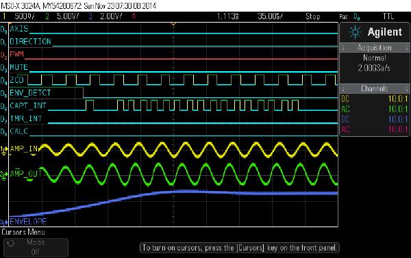
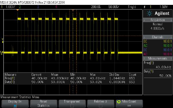
In my last post I talked about how to get the Arduino to output bursts of 40kHz pulses. Today I’ll go through the rest of the software so by the end of this post we’ll have a very rudimentary but working sketch for our ultrasonic wind meter.
Today I’ll tell you how I got started with my software. If you’re new to my blog you might want to click here for an overview over my arduino-based wind meter project: /projects/arduino-ultrasonic-anemometer/