In my last post I was happy to report that I managed to get the USB interface to work. This interface has since proved to be extremely valuable in software development and testing. While the device is taking measurements you can look at the results (or intermediate results) at your PC in real time. You can even log large amounts of data to a .csv file and inspect the results in Excel.
Last time I showed you the nice new hardware of the new standalone ultrasonic anemometer. But at that time I had hardly any software written for it so I couldn’t do much with its 32 bit microcontroller. So the last two or three weeks I spend lots of time writing code that I’d like to share with you today.
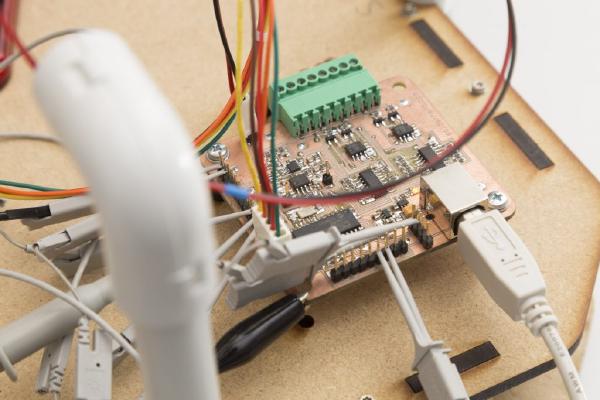
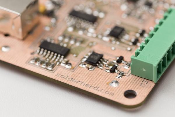
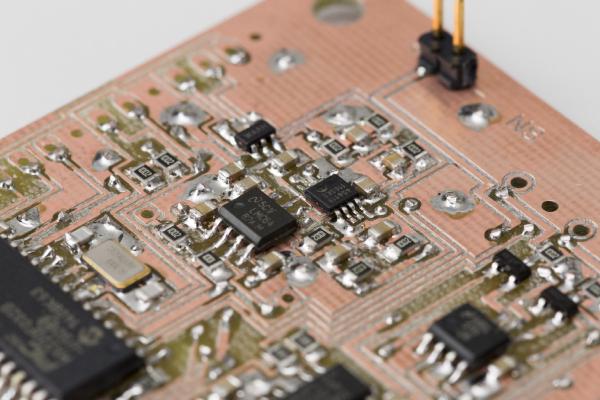
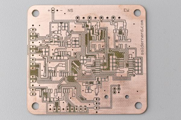
Last time I went through the design of my new standalone anemometer. Now it’s time to build this thing and see if it works as planned.
After I fried a couple of chips on my driver circuit testing board due to a wrong chip in the power supply I was a bit more careful this time and built up the board step by step.
Last time I outlined my reasons to ‘go digital’ by adding a powerful on-board microcontroller and designing a standalone wind meter.
In the weeks that followed that decision I tried to find a suitable microcontroller and to design a prototype. Today I’ll show you the result of that work.