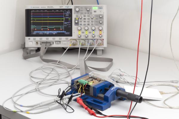
Last time I’ve presented my new design for the ultrasonic anemometer driver circuit. So now it’s time to see how it performs. If you’re new to this project you might want to check out the overview page or at least my last post.
It’s been about one and a half years since I started out with my ultrasonic anemometer project. Like others before me I had to notice that this a much more demanding project than it appears to be at first. After countless hours of development and testing I have built this Arduino shield. It worked but the reliability of the measurements was never what I had aimed for. The problem was mainly how to figure out the absolute phase of the received signal. So the measurements were always precise - but sometimes off by a full wavelength. Then I was more or less inactive for most of 2015, mainly due to personal reasons. So the project was kind of stuck but i kept (and keep) getting a lot of encouraging feedback from you folks. I came up with new circuit ideas and decided to pretty much start with an entirely new design and to re-think each and every design choice I had made back then.
Finished RGB dimmer In my last post I’ve described the design and construction of my LED dimmer project. This project here is similar but a bit more involved. It controls RGB LEDs so it can not only change the brightness but also the color of the light. Instead of a simple pot it used a pair of rotary encoders with push buttons. One controls the brightness, pushing its button turns the light on or off. The other changes the color, pushing its button toggles between color and white.
Finished LED dimmer I have recently moved to a new apartment and was looking for a PWM dimmer to control some 12V LED strips. I thought that should be easy enough nowadays but it proved more difficult than I thought. All I found either didn’t meet my requirements, were uggly or expensive. So I decided to build my own, tailor-made to my needs.
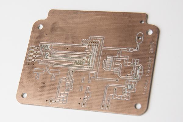
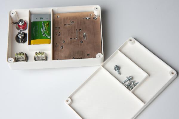
When I made the PCB for the stand-alone inductance meter, I erroneously used a SSOP footprint for the microcontroller (instead of the desired SOIC). The PIC is available in a SSOP package (PIC16F1963-I/SS instead of PIC16F1936-I/SO) but I didn’t have any at hand so I simply made a new board with a SOIC footprint.
If you’ve read my last post you’re already familiar with my Inductance Meter project: /posts/stand-alone-inductance-meter/. At that time the hardware was ready but there was no software yet. That’s been corrected, the inductance meter is now fully functional.
Some of you may have seen my arduino-based inductance meter in this post: /posts/arduino-based-inductance-meter/. The guys at dangerousprototypes.com picked it up (http://dangerousprototypes.com/2014/12/16/arduino-based-inductance-meter/) and this blog got more visitors than I could ever have imagined. Thanks, dangerousprototypes.