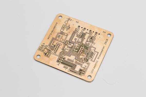
It’s been about one and a half years since I started out with my ultrasonic anemometer project. Like others before me I had to notice that this a much more demanding project than it appears to be at first. After countless hours of development and testing I have built this Arduino shield. It worked but the reliability of the measurements was never what I had aimed for. The problem was mainly how to figure out the absolute phase of the received signal. So the measurements were always precise - but sometimes off by a full wavelength. Then I was more or less inactive for most of 2015, mainly due to personal reasons. So the project was kind of stuck but i kept (and keep) getting a lot of encouraging feedback from you folks. I came up with new circuit ideas and decided to pretty much start with an entirely new design and to re-think each and every design choice I had made back then.
Finished RGB dimmer In my last post I’ve described the design and construction of my LED dimmer project. This project here is similar but a bit more involved. It controls RGB LEDs so it can not only change the brightness but also the color of the light. Instead of a simple pot it used a pair of rotary encoders with push buttons. One controls the brightness, pushing its button turns the light on or off. The other changes the color, pushing its button toggles between color and white.
Finished LED dimmer I have recently moved to a new apartment and was looking for a PWM dimmer to control some 12V LED strips. I thought that should be easy enough nowadays but it proved more difficult than I thought. All I found either didn’t meet my requirements, were uggly or expensive. So I decided to build my own, tailor-made to my needs.
First tests are being performed on the Solar Charger Shield In my last post I’ve introduced a proof-of-concept Arduino solar charger shield. I went through the hardware as well as the way it works - or at least is intended to work. It was prominently linked on dangerousprototypes.com as well as some other sites and got quite a bit of publicity as a result. Thank you all for sharing this post.
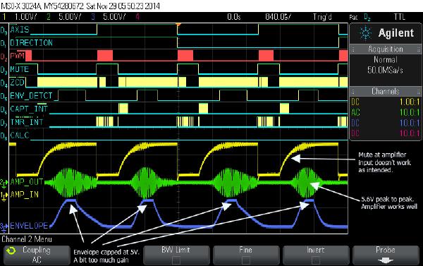
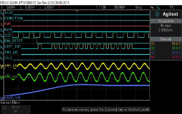
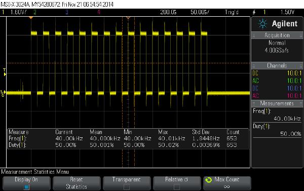
Today I’ll go through each part of my new Arduino shield to see if it performs as expected.
If you’re new to my Arduino-based ultrasonic wind meter project, you might want to click here for an overview: /projects/arduino-ultrasonic-anemometer/
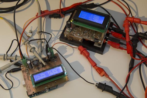
My first wind meter prototype is kind of working. The software will need improvement to make this wind meter into something really useful. But both hardware and software are basically functional and can be built up upon.
In my last post I talked about how to get the Arduino to output bursts of 40kHz pulses. Today I’ll go through the rest of the software so by the end of this post we’ll have a very rudimentary but working sketch for our ultrasonic wind meter.
Today I’ll tell you how I got started with my software. If you’re new to my blog you might want to click here for an overview over my arduino-based wind meter project: /projects/arduino-ultrasonic-anemometer/
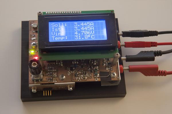
This is a constant current dummy load. It’s controlled by a PIC16F1936 microcontroller. As you can see, it’s equipped with a 4x16 character LCD display and, less obvious, a rotary encoder with push button. It accurately sets the desired current via a 16bit DAC and reads both current and input voltage with a single-channel 16bit ADC each. Temperature is measured by the microcontroller’s internal 10bit ADC.