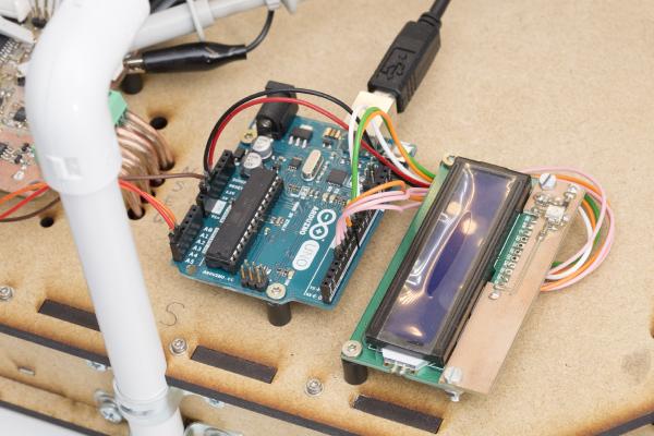
It’s been a long six weeks since my last post but that doesn’t mean that I haven’t done anything since. Among other things, I wrote some code to get the I2C interface working and hooked the anemometer up to an Arduino Uno with an LCD display attached. Apart from demonstrating the I2C interface this also nice for testing. For the first time I can see what this thing is measuring in real time without hooking it up to a PC over USB.
It’s been almost three weeks since my last post and some further progress has been made. I’ve upgraded the microcontroller and can now control the gain of the second amplifier stage in software. But let’s look at the changes in some more detail.
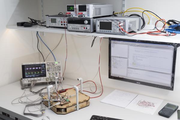
In my last post I was happy to report that I managed to get the USB interface to work. This interface has since proved to be extremely valuable in software development and testing. While the device is taking measurements you can look at the results (or intermediate results) at your PC in real time. You can even log large amounts of data to a .csv file and inspect the results in Excel.
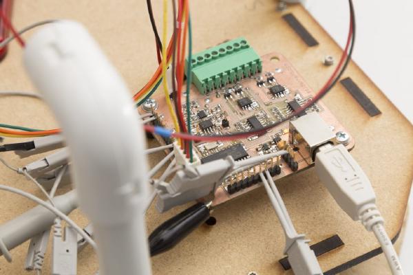
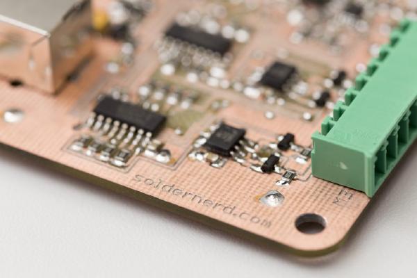
Last time I showed you the nice new hardware of the new standalone ultrasonic anemometer. But at that time I had hardly any software written for it so I couldn’t do much with its 32 bit microcontroller. So the last two or three weeks I spend lots of time writing code that I’d like to share with you today.
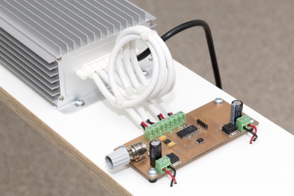
Finished LED dimmer I have recently moved to a new apartment and was looking for a PWM dimmer to control some 12V LED strips. I thought that should be easy enough nowadays but it proved more difficult than I thought. All I found either didn’t meet my requirements, were uggly or expensive. So I decided to build my own, tailor-made to my needs.
I regularly use PIC microcontrollers. I’ve tried some Atmel chips lately but I’m still by far most familiar with the PIC16 & PIC18 chip families. As you can see in my other posts, I tend to use SMD components but once in a while I need to program a DIP package.