Recently, I’ve sucessfully tested the new driver ciruit for my ultrasonic anemometer. It performed even better than I expected and I will be happy to use it pretty much as it is.
Today I’ll go through each part of my new Arduino shield to see if it performs as expected.
If you’re new to my Arduino-based ultrasonic wind meter project, you might want to click here for an overview: /projects/arduino-ultrasonic-anemometer/
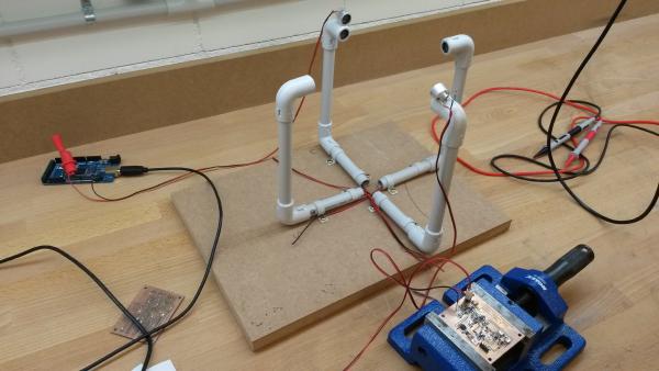
My first wind meter prototype is kind of working. The software will need improvement to make this wind meter into something really useful. But both hardware and software are basically functional and can be built up upon.
In my last post I talked about how to get the Arduino to output bursts of 40kHz pulses. Today I’ll go through the rest of the software so by the end of this post we’ll have a very rudimentary but working sketch for our ultrasonic wind meter.
In this post I will go through the testing of the analog circuit and what I had to do to make it work properly. Click here for an overview over this series of posts on the anemometer project: /projects/arduino-ultrasonic-anemometer/
Today I’ll go through the details of the analog cirquit. Click here for an overview over this series of posts on the anemometer project: /projects/arduino-ultrasonic-anemometer/
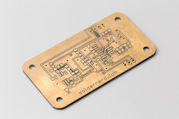
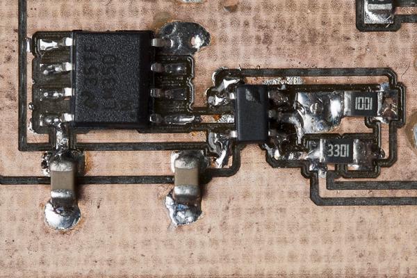
The analog board ready to be connected This is what I would consider the heart of this wind meter. This is where the received signal is amplified and processed so the overall accuracy and reliability of the entire project really depends on it. The functionality of this board can be summarized as follows: