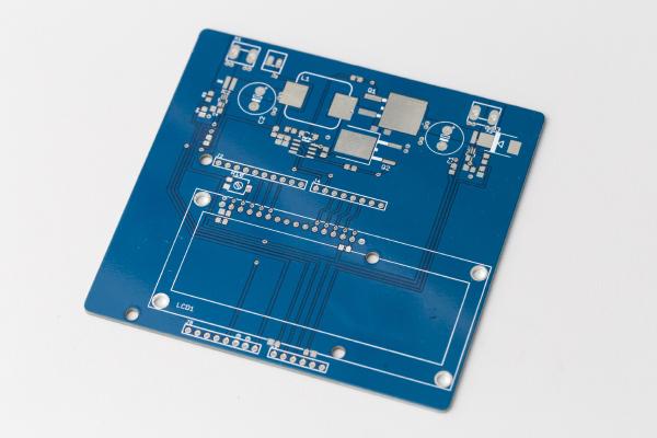
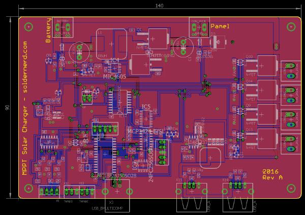
A reader of this blog was so kind to send me a number of surplus boards of two of my solar charger designs. Thank you, Joachim.
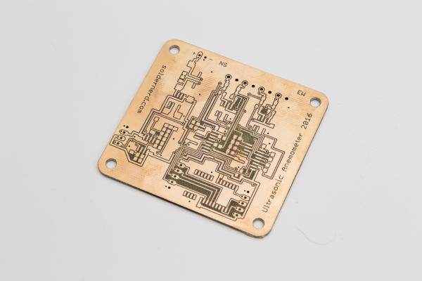
I’m currently waiting for the boards for my Ultrasonic Anemometer Rev B to arrive from Hong Kong and this gives me some time to write about the MPPT Solar Charger design that I did quite some time ago. I published a series of posts on a Arduino MPPT Solar Charger Shield and got a lot of encouraging feedback. But that shield was more of a proof-of-concept than a finished product. While it generally performed well it drew way too much current when idle to actually be deployed unless you can count on plenty of sunshine every day.
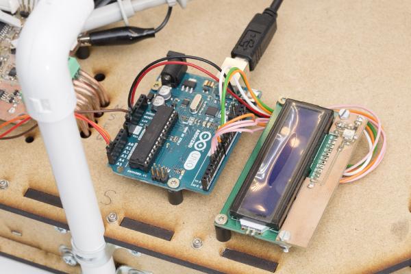
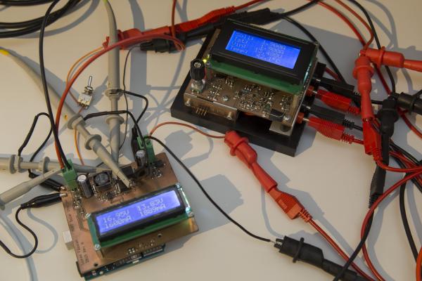
It’s been a long six weeks since my last post but that doesn’t mean that I haven’t done anything since. Among other things, I wrote some code to get the I2C interface working and hooked the anemometer up to an Arduino Uno with an LCD display attached. Apart from demonstrating the I2C interface this also nice for testing. For the first time I can see what this thing is measuring in real time without hooking it up to a PC over USB.
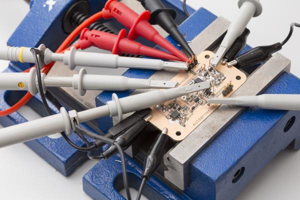
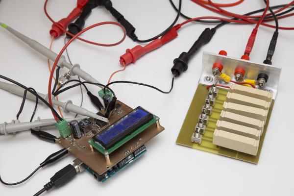
In my last post I went through the design of the analog part of the ultrasonic anemometer. Today we will see how the circuit designed last time performs in practice.
In my last two posts I have gone through my new anemometer circuit both in theory and practice. Click here for an overview over my ultrasonic anemometer project.
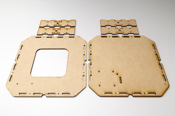
It’s been about one and a half years since I started out with my ultrasonic anemometer project. Like others before me I had to notice that this a much more demanding project than it appears to be at first. After countless hours of development and testing I have built this Arduino shield. It worked but the reliability of the measurements was never what I had aimed for. The problem was mainly how to figure out the absolute phase of the received signal. So the measurements were always precise - but sometimes off by a full wavelength. Then I was more or less inactive for most of 2015, mainly due to personal reasons. So the project was kind of stuck but i kept (and keep) getting a lot of encouraging feedback from you folks. I came up with new circuit ideas and decided to pretty much start with an entirely new design and to re-think each and every design choice I had made back then.
There have been two previous posts on this project: one on the concept and the hardware and one on hardware testing. You probably want to check them out first if you’re not yet familiar with this project. Or even better: Click here for an overview over this project.
First tests are being performed on the Solar Charger Shield In my last post I’ve introduced a proof-of-concept Arduino solar charger shield. I went through the hardware as well as the way it works - or at least is intended to work. It was prominently linked on dangerousprototypes.com as well as some other sites and got quite a bit of publicity as a result. Thank you all for sharing this post.
A friend has approached me regarding his solar project. He wants to install a solar panel together with a battery and an inverter in order to have power at his allotment garden. He had looked at a hobbyist project where an arduino was used to build a MPPT (maximum point of power tracking) charge controller. I took a look at the design, liked a lot of what I saw and decided to build something similar.
Finished 5V to 12V USB boost converter I frequently need a low-power supply to run a microcontroller system. Typically, one uses a lab power for such purposes. But at least on the desk where I do the programming I don’t have one. Since these systems typically consume little current it would be handy to be able to power them from USB. Most of my devices have on-board regulators so the voltage is rather uncritical. For 3.3 volt devices, the 5V from USB is just right. But others have a 5V regulator so they need a higher supply voltage. And even others might even need 12 volts.