A reader of this blog was so kind to send me a number of surplus boards of two of my solar charger designs. Thank you, Joachim.
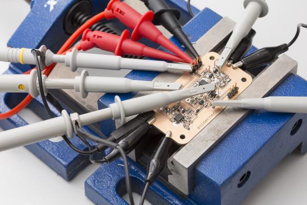
In my last post I went through the design of the analog part of the ultrasonic anemometer. Today we will see how the circuit designed last time performs in practice.
A friend has approached me regarding his solar project. He wants to install a solar panel together with a battery and an inverter in order to have power at his allotment garden. He had looked at a hobbyist project where an arduino was used to build a MPPT (maximum point of power tracking) charge controller. I took a look at the design, liked a lot of what I saw and decided to build something similar.
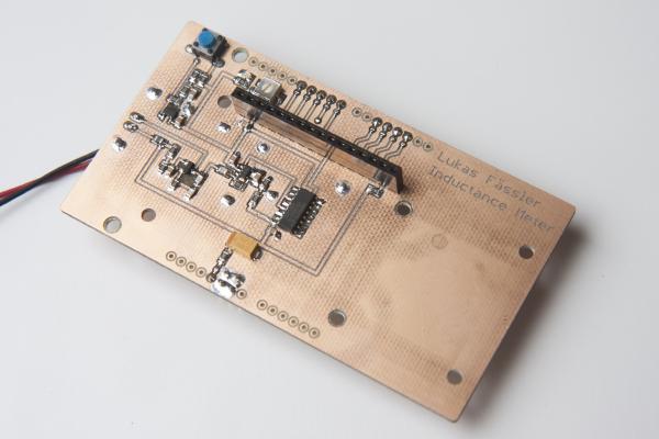
Incuctance meter in action. It displays the resonance frequency together with the inductance I’ve just finished a little Arduino project. It’s a shield for the Arduino Uno that lets you measure inductance. This is a functionality that I found missing in just about any digital multi meter. Yes, there are specialized LCR meters that let you measure inductance but they typically won’t measure voltages or currents. So I had to build my inductance meter myself.
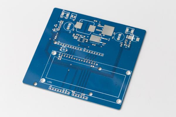
A world’s first: Ultrasonic Anemometer Shield for Arduino Uno I’m happy to announce that my new Arduino wind meter shield is ready. I had posted the design as well as a photo or two of the naked board in my last post but now I’ve placed and soldered all the numerous components and it’s ready to go.