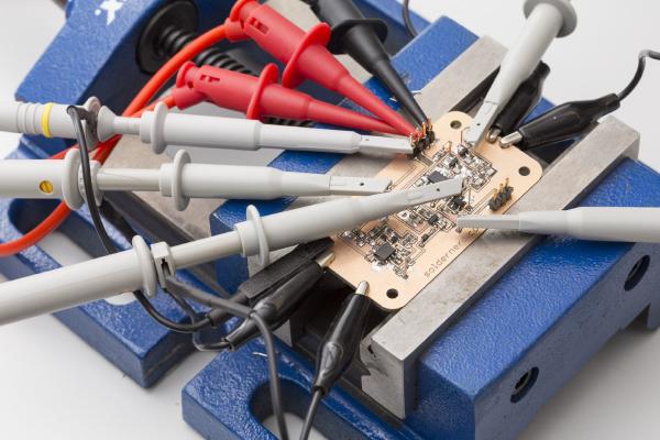
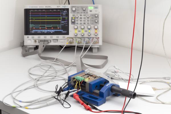
In my last post I went through the design of the analog part of the ultrasonic anemometer. Today we will see how the circuit designed last time performs in practice.
Recently, I’ve sucessfully tested the new driver ciruit for my ultrasonic anemometer. It performed even better than I expected and I will be happy to use it pretty much as it is.
Last time I’ve presented my new design for the ultrasonic anemometer driver circuit. So now it’s time to see how it performs. If you’re new to this project you might want to check out the overview page or at least my last post.
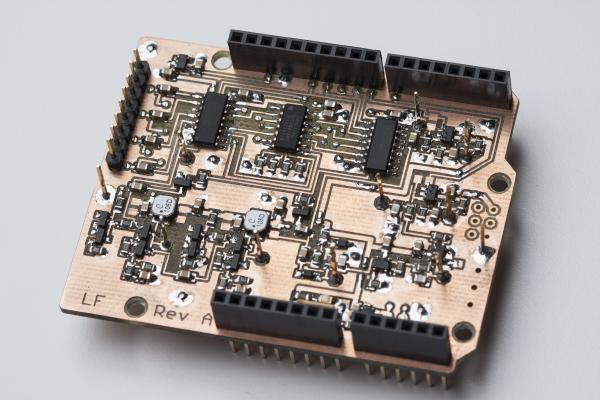
It’s been about one and a half years since I started out with my ultrasonic anemometer project. Like others before me I had to notice that this a much more demanding project than it appears to be at first. After countless hours of development and testing I have built this Arduino shield. It worked but the reliability of the measurements was never what I had aimed for. The problem was mainly how to figure out the absolute phase of the received signal. So the measurements were always precise - but sometimes off by a full wavelength. Then I was more or less inactive for most of 2015, mainly due to personal reasons. So the project was kind of stuck but i kept (and keep) getting a lot of encouraging feedback from you folks. I came up with new circuit ideas and decided to pretty much start with an entirely new design and to re-think each and every design choice I had made back then.
It’s been a while since I posted the last update on the anemometer project. The reason for this is that I’m struggling with the aerodynamical design.
By the way: Click here for an overview over the ultrasonic anemometer project: /projects/arduino-ultrasonic-anemometer/
It’s been a while since the last post of this series. As so often, the task turned out to be more demanding than I first thought. And then I was also entirely new to assembly language, got distracted by my Inductance Meter Project (/posts/arduino-based-inductance-meter/) and went on a skiing holiday. But finally, the promised library is ready.
This is just a very brief update on what I’ve been working on the last few days. By now, this blog has caught up with where the project currently stands so the blog posts won’t be quite as frequent as they used to be. When I just started this series I had already worked on this my wind meter project for two months so I had plenty of material I only had to post.
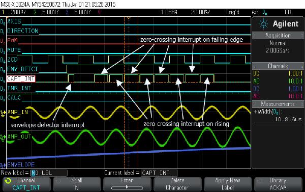
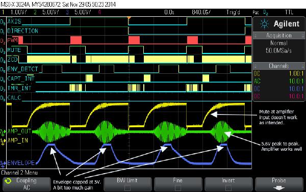
Today I’ll go through each part of my new Arduino shield to see if it performs as expected.
If you’re new to my Arduino-based ultrasonic wind meter project, you might want to click here for an overview: /projects/arduino-ultrasonic-anemometer/
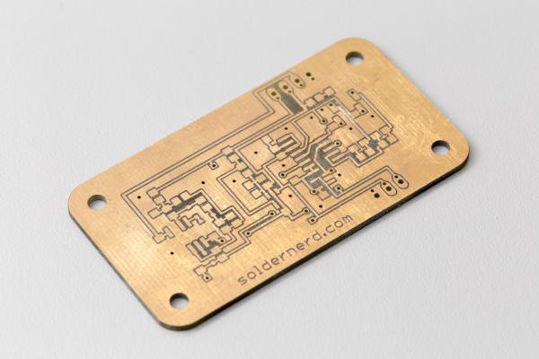
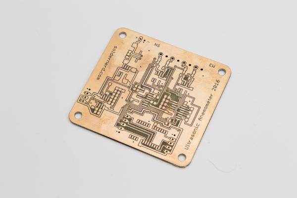
A world’s first: Ultrasonic Anemometer Shield for Arduino Uno I’m happy to announce that my new Arduino wind meter shield is ready. I had posted the design as well as a photo or two of the naked board in my last post but now I’ve placed and soldered all the numerous components and it’s ready to go.
My first wind meter prototype is kind of working. The software will need improvement to make this wind meter into something really useful. But both hardware and software are basically functional and can be built up upon.