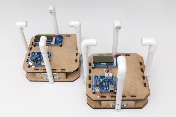
In my last post of this series I’ve looked at different transducers and finally decided on a entirely waterproof 14mm model. The much lower signal level from those kind of transducers makes it necessary to reduce the distance between the transducers in order to still receive a reasonable signal amplitude. So I took my previous lasercut design and reduced it in size so that the distance between the transducers is only 120mm. I went to the local FabLab and and lasered two copies of the downsized design.
I last time proudly presented the new RevB board and got a lot of feedback from people who want one, too. As mentioned I have all the components here to ship up to 10 kits but I was reluctant to send anything until I had the chance to do some hardware testing. Not much had changed since the last revision but I don’t like taking chances on things like this.
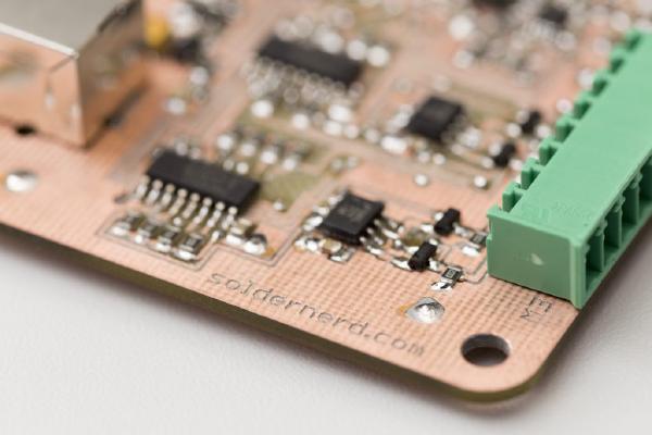
Good news: the boards from dirtypcbs.com have arrived and look great. I also got all the components for the 11 boards. Why 11? I ordered about 10 (they call it a protopack) and was lucky enough to get 11. Thats dirtypcbs.
I recently ordered my first PCB at dirtypcbs.com and the result was promising. So there was nothing stopping me from finalizing the Rev B of my standalone Ultrasonic Anemometer and ordering a protopack. I’ve placed the order a few days ago and expect the boards to arrive here in 2 to 3 weeks. This should be good news for all those of you who have been asking for kits and want to contribute to the further developement of this project. I’ll build up one or two boards as soon as they get here and do some testing. If everything works as planned I can order some more components and ship some kits soon after that.
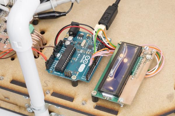
It’s been a long six weeks since my last post but that doesn’t mean that I haven’t done anything since. Among other things, I wrote some code to get the I2C interface working and hooked the anemometer up to an Arduino Uno with an LCD display attached. Apart from demonstrating the I2C interface this also nice for testing. For the first time I can see what this thing is measuring in real time without hooking it up to a PC over USB.
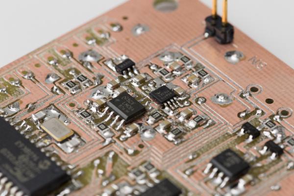
It’s been almost three weeks since my last post and some further progress has been made. I’ve upgraded the microcontroller and can now control the gain of the second amplifier stage in software. But let’s look at the changes in some more detail.
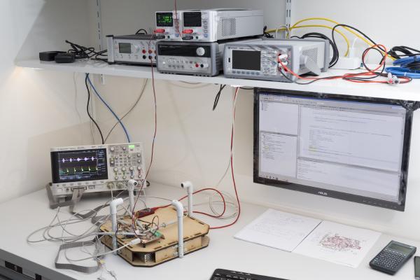
In my last post I was happy to report that I managed to get the USB interface to work. This interface has since proved to be extremely valuable in software development and testing. While the device is taking measurements you can look at the results (or intermediate results) at your PC in real time. You can even log large amounts of data to a .csv file and inspect the results in Excel.
Last time I showed you the nice new hardware of the new standalone ultrasonic anemometer. But at that time I had hardly any software written for it so I couldn’t do much with its 32 bit microcontroller. So the last two or three weeks I spend lots of time writing code that I’d like to share with you today.
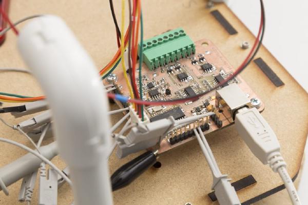
Last time I went through the design of my new standalone anemometer. Now it’s time to build this thing and see if it works as planned.
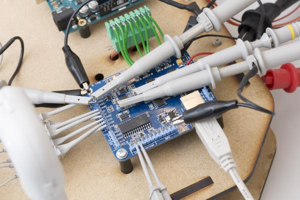
After I fried a couple of chips on my driver circuit testing board due to a wrong chip in the power supply I was a bit more careful this time and built up the board step by step.
Last time I outlined my reasons to ‘go digital’ by adding a powerful on-board microcontroller and designing a standalone wind meter.
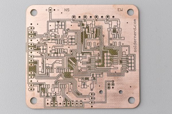
In the weeks that followed that decision I tried to find a suitable microcontroller and to design a prototype. Today I’ll show you the result of that work.