
In the last post I went through the analog board and showed what I had to do to get it working properly. Today I’ll do the same whith the digital board. Click here for an overview over this series of posts on the anemometer project: https://soldernerd.com/arduino-ultrasonic-anemometer/

So I plugged in the board for the first time and everything looked fine. The power LED came on, both the +5V and -5V rails worked as expected. But not everything worked that well.
I’ve explained in a previous post how the Arduino can control the direction by means of two lines: Axis and Direction. Here’s the meaning of these signals (L=low, H=high):
Axis=L, Direction=L -> North to South
Axis=L, Direction=H -> South to North
Axis=H, Direction=L -> East to West
Axis=H, Direction=H -> West to East
The first thing these two signals do is to control 74HC139 address decoder. The 139’s enable signal is grounded so its outputs are always on. Depending on Axis and Direction the 139 turns exactly one of the signals North_EN, South_EN, East_EN and West_EN on. EN stands for enable. As the bar over the signal name indicates, these are active-low signals. So zero volts means on and 5V means off. Each of these enable signals is connected to an LED. The other side of the LEDs is connected (via a resistor of course) to +5V so the LED is on when the signal is on despite the fact that it is active low. This part also worked.
Then we have two 74HC368 hex inverters. If you look at the 368s data sheet you’ll notice that it consists of 6 inverting buffers. But there are only two enable signals. As with most enable signals, these too are active-low. One enable signal controls 4 of the inverting buffers while the other one controls only 2. For us, this doesn’t matter since we need a total of 4 groups (one for each transducer) of 2 buffers each (one for each transducer pin). So we’ll only use two buffers of each group no matter if there are four.
Each group is controlled by one of the enable signals coming from the 139. The North_EN signal enables the buffers of the group connected to the North transducers and so forth. So exactly one group of buffers is on at any given time. That’s the transducer that is transmitting. All 4 buffer groups are connected to the same PWM signal (named Signal on the schematic) coming from the Arduino. But since only one buffer group is on, only that transducer is actually sending. The other buffer outputs are off and their transducer pins can float freely. Notice how the PWM signal is connected to the input of only one of the buffers in each group. The output of that buffer ist then connected a transducer pin as well as to the input of a second buffer. So one pins of the transmitting transducer are always in opposite states. When the first one is high, the second one is low and vice versa. There were no surprises here, everything worked as expected.
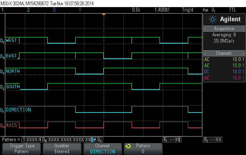
Here’s a little visualization of the 74HC139 in action. Note the glitches in the West_EN and East_EN signals. The Arduino can’t change both Axis and Direction perfectly simultaneously, there will always be at least one clock cycle in between the two commands. That’s why those glitches happen. But Axis and Direction are changed between measurements so nothing interesting is going on anyway. No need to worry about this here.
But then there is the task of selecting the right signal to listen to. And that’s where I’ve messed up just about everything. I guess I just wanted to build my first prototype as soon as possible and didn’t double-check everything as I should have. I probably also tried to be clever and use as few signals as possible and chose my inputs so that it simplifies the physical routing on the PCB. Anyway, I ended up with a design that doesn’t work. So if you want to build this circuit, look at the RevB board and schematics where I’ve corrected the mistakes.
As explained before, there are three 74HC4052 multiplexers to eliminate crosstalk. Like the 139, the 4052s are controlled by Axis and direction. But watch out: You need to select the transducer opposite from the one that is transmitting. So for example Axis=L and Direction=L means North to South. North_EN is low so the North buffer group is on and so North is transmitting. That means we have to chose the South transducer for receiving. Nothing complicated, really. But you have to concentrate and think carefully about which transducer has to connected to which of inputs. There are multiple solutions that work but many more that don’t.
My working solution is as follows: IC5 selects between North and East. So North is connected to input 1 while East is connected to input 3. When we want to listen to North, East is idle and vice versa. That’s why we get rid of crosstalk. The negative output of IC5 is grounded, the positive one is named NorthEast and routed to IC6. The second multiplexer, IC7 selects between South on input 0 and West on input 2. Again, the negative output is grounded and the positive output named SouthWest is connected to IC6. IC6 then only has the simple task of choosing between SouthWest and NorthEast. That’s why I only needed my Direction signal to control this multiplexer. The other address input can be left grounded.
I didn’t bother building another board so I’ve just used some pieces of wire to correct my mistakes. The corrected circuit is equivalent to what you see on the RevB schematic and works flawlessly.
This was definitely not my most interesting post so far. Lots of text and much in the way of photos or screenshots. Analog circuits are usually more fun to work with I find. Next time I’ll connect the Arduino to my two boards and show you how they perform. There will be some photos and screen shots again, promise.
Click here for the next post: https://soldernerd.com/2014/11/19/arduino-ultrasonic-anemometer-part-6-mechanical-design/