Part 3 of my Tripet MHP 500 restoration series. In Part 2 I got the electrics sorted and the spindle rebuilt. This time it was table off, cross-slide out, and a proper look at what’s underneath. Overview page: /projects/tripet-mhp-500/.
The table comes off#
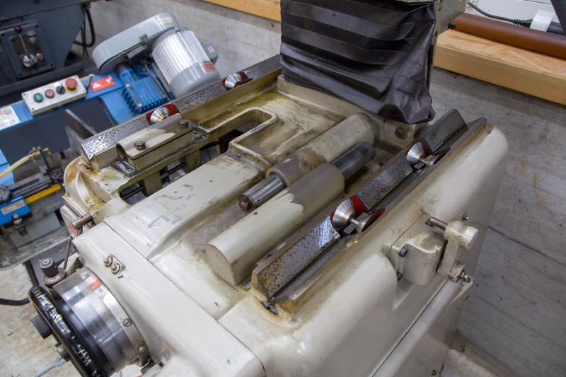
Lifting the pendulum table off a 60-year-old machine is usually when you find a sad heap of rust underneath. Not this time. Magnetic chuck off, then the table lifts straight off - nothing to unbolt, no hoses to drain. The photos below were taken within seconds of it coming off, before any cleaning.
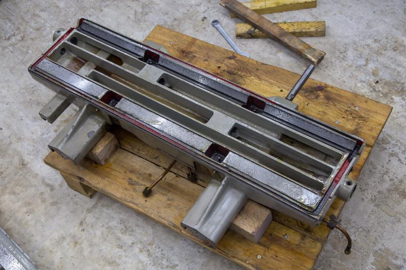
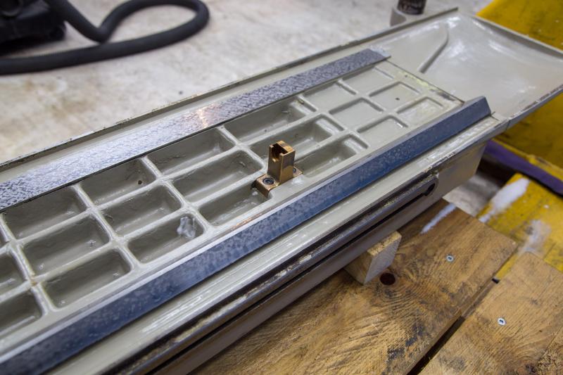
Once it was properly cleaned, the guideways looked even better than that first look suggested. The only surface with real wear is the front chamfered face; the rest is in good shape. The light rust on the front came off with WD-40 and a Scotch-Brite pad - nothing more aggressive needed.
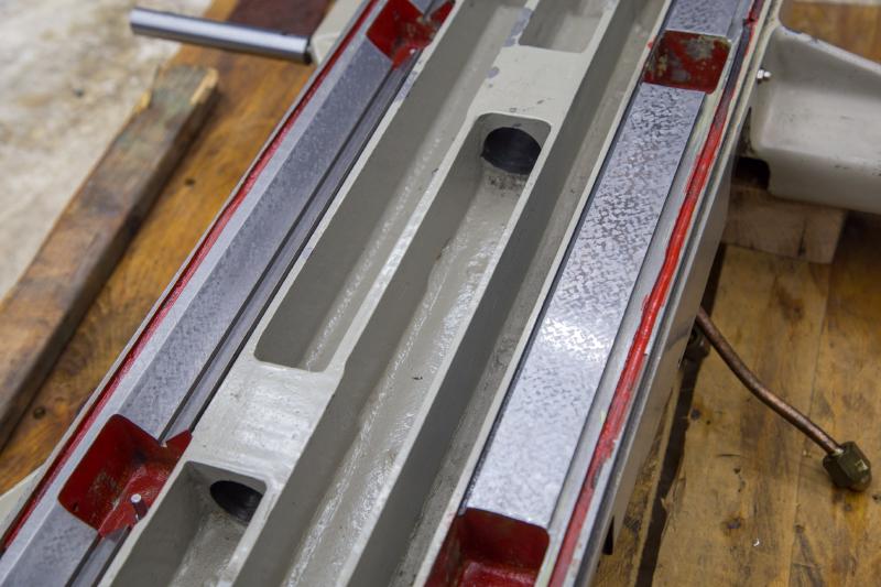
The lubrication is simple: rollers running in an oil bath underneath, lightly touching the way, dragging oil up as they turn. The actual weight of the table runs on the scraped surfaces, not on the rollers.
The table itself is surprisingly light at 57 kg - light enough, presumably, to be thrown back and forth at pendulum-stroke speed without shaking the whole machine.
Cross-slide out#
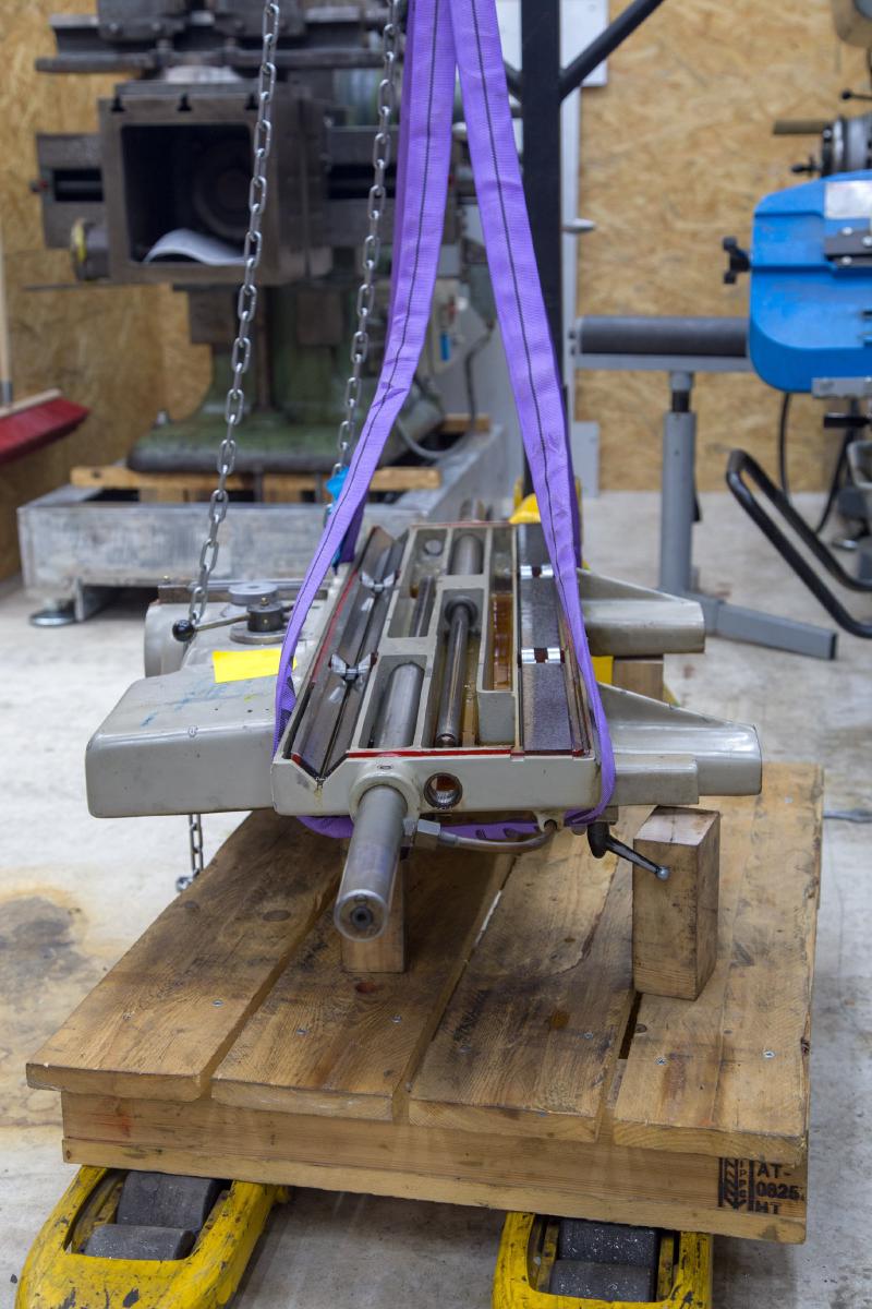
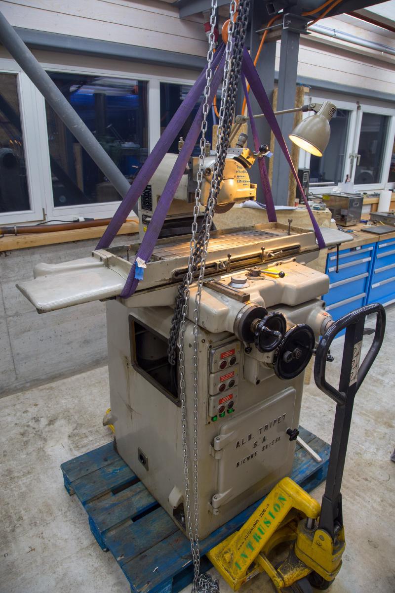
Taking the cross-slide off was also easier than expected - one hydraulic hose to disconnect and that was it. At 93 kg it’s a lot heavier than the table, but nothing a small crane can’t handle. Underneath, it wasn’t quite as clean as under the table. The manual wants the pendulum table fully lifted off for cleaning every two weeks, while the cross only gets lifted a few centimetres to wipe the ways. This avoids disconnecting the hydraulics but also means the cleaning will be basic at best.
The cross-spindle had about 1 mm of axial play and came apart following the manual: handwheel off (there’s a taper pin), loosen the two screws on the nut, nut and dial off, then the three screws underneath, release the clamp lever, and pull the whole assembly out.
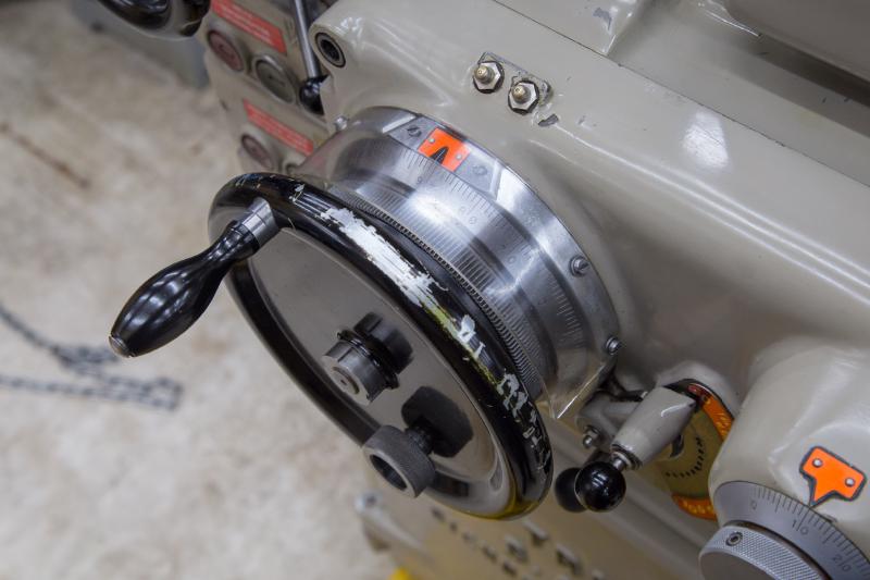
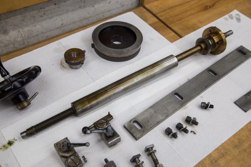
It cleaned up nicely and the axial play came out with it.
Machine feet, because I need to wheel it around#
I need to be able to move this machine around with a pallet truck, which means at least 80-90 mm of clearance under the base. I got M16 machine feet for it - steel only, no rubber or felt, because the manual is emphatic about not putting anything soft under the machine.
On the feet alone it sat quite high, so I made long counter nuts out of 40 mm round stock: drilled through, tapped M16 at one end, bored 19 mm at the other, then milled a 36 mm hex on each with the UB2.
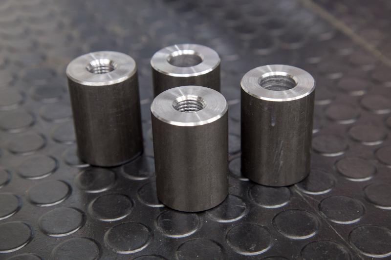
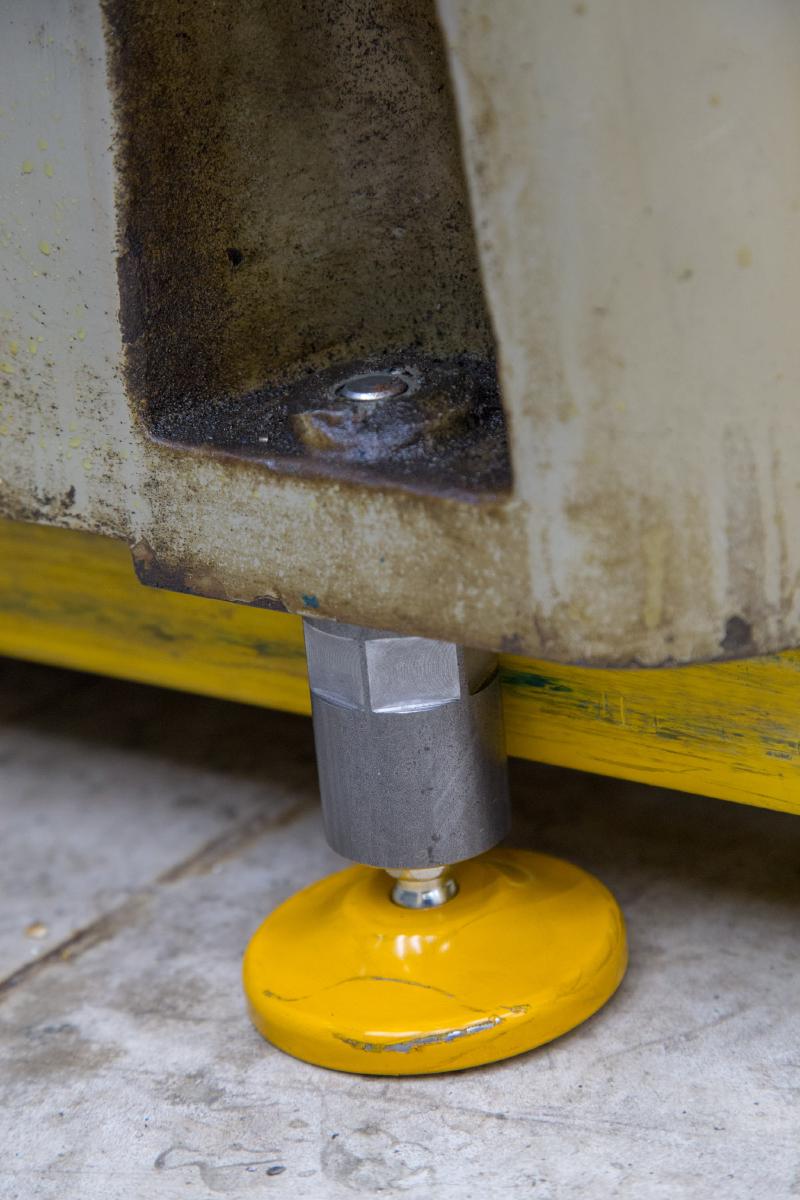
They screw down onto the feet and lock everything in place. Clearance for the pallet truck is tight, but it fits - and the machine stands like it’s bolted to the floor.
Hydraulic cylinders: two parts, no seals#
There’s a small Tripet puzzle with the longitudinal drive: two hydraulic cylinders drive the table in X, but they only actively extend - on the return stroke they get pushed back passively by the other cylinder. With the circuit open they slide smoothly by hand, but only for the first 450 mm of the 500 mm stroke. After that they start to clamp up, which had caused the table to jam at the end of travel a few times.
Taking them apart is supposed to be a bad idea, according to another Tripet owners, and he was probably right - but one of mine came apart in my hand anyway, all the oil ran out, and my first instinct was to just shove the piston back in. At that point I was already committed, so both cylinders came out and got stripped properly.
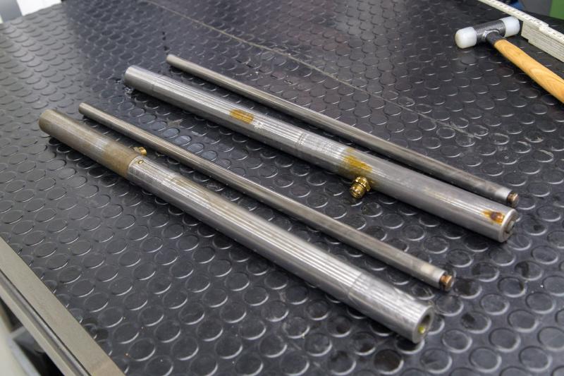
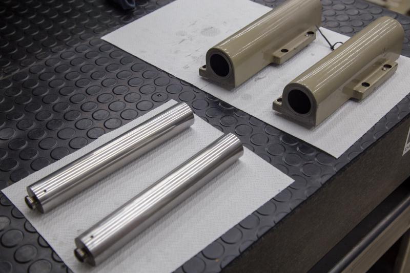
The part that surprised me: the hydraulic cylinder is just two pieces of metal, piston and bore. No seal, no wiper, no O-ring, no nothing. The fit is precise enough that it doesn’t need more - lapped probably, and tight by pure geometry. Nobody would design it that way today, but it’s held up for sixty years and still does not leak.
To put them back together was smoother than expected, I laid it all out on the surface plate on V-blocks to not tilt anything, washed my hands, oiled the bores, and fed each piston in gently. Both went together first try and now slide smoothly end to end.
Taking off the Z-axis#
The hydraulic was ready, the cylinders worked smoothly, the table was clean. Things were going well. Then, I decided to take the column off as well.
My thought: just ceep cranking, at some point you run out of thread and I can just lift it off. But the spindle nut jammed itself into the column before that.
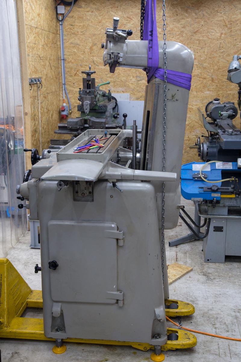
I secured the head, loosened the rear clamping strips a little (and noticed two missing screws in the process) and tried to get the column lose again
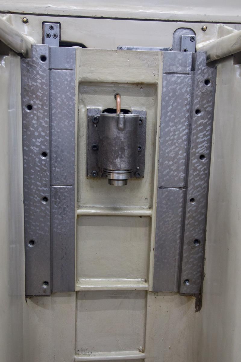
Because of how the Z-drive is built - the leadscrew is fixed and the nut rotates, driven through a bevel gearbox - both ends were accessible, so nothing was actually unrecoverable. It was just going to take some work.
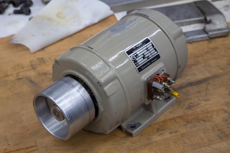
Pulling the Z-motor was a real fiddle, and once it was out I got my first bad surprise.
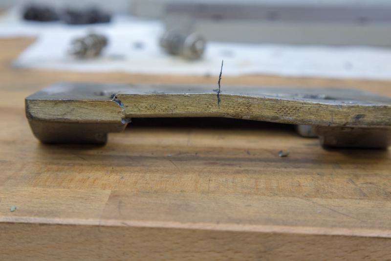
That’s where I’ll pick up in Part 4, along with the coolant trolley and the first real grinds.