Part 2 of my Tripet MHP 500 restoration series. In Part 1 I picked up the machine and got as far as tripping the RCD on first power-on. The overview for the series is at /projects/tripet-mhp-500/.
The electrical mystery#
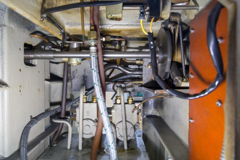
The machine has no neutral conductor - just three phases and earth, which is normal for three-phase industrial equipment of this era. The control lamps are wired phase-to-phase accordingly, and that part was fine.
The problem was a solenoid valve with its return conductor connected to earth rather than to a proper neutral. That put about 600 Ω from one phase to earth, enough to trip the RCD before anything else could happen.
The fix was to replace the mains cable with a five-conductor one to add a neutral, then move the solenoid’s return from earth to neutral. After that, the hydraulics ran without complaint. The solenoid valve bypasses oil between the two X cylinders when switching from hydraulic X-travel to the manual Y handwheel.
One real problem remained: the spindle.
Taking the spindle apart#
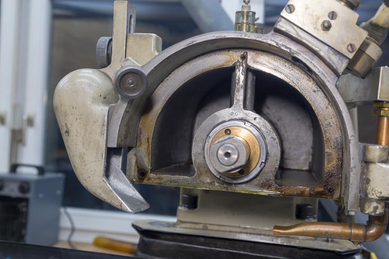
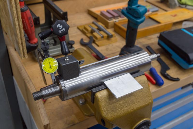
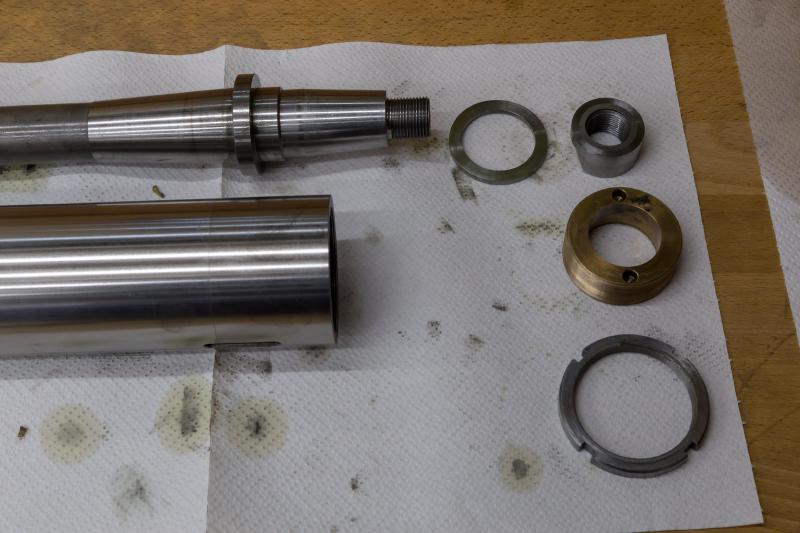
There was a ton of axial play in the spindle. I could rock it back and forth by maybe a milimeter. Removing the spindle was straightforward. With the sheet metal off I undid the front bronze nut and its locknut, removed the belt pulley, and the shaft slid out forward. One grub screw at the underside of the head and the whole spindle cartridge followed. The rear tapered bearing shell with its needle bearing came off with an internal puller and a slide hammer.
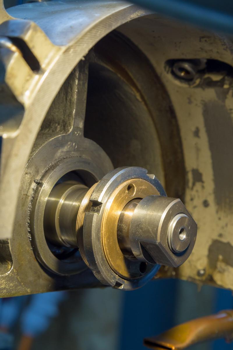
The needle bearing at the back does not set the spindle’s running accuracy - it only carries the belt load. Both radial and axial accuracy come from the scraped conical bronze bearing at the front. The ~1 mm of axial play I could feel when I first moved the spindle by hand were not that taper’s fault. The back end of the spindle had simply worked loose and the shaft was no longer properly pulled into the taper.
Cleaning and reassembly#
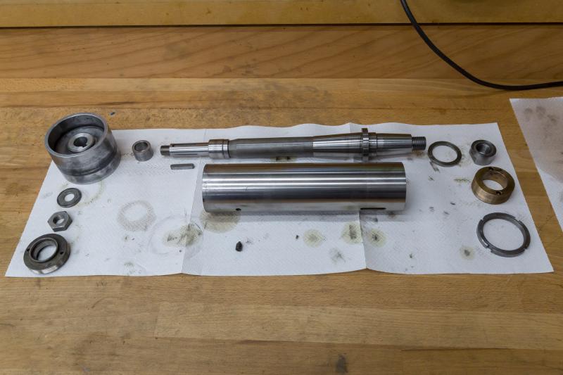
No ultrasonic cleaner available, so everything was cleaned by hand, oiled, and put back together. The manual covers the build sequence and preload adjustment in detail, and it is worth following. The key point is that the cartridge can be set up and measured on the bench - once it is back in the head, the rear needle bearing is nearly unreachable.
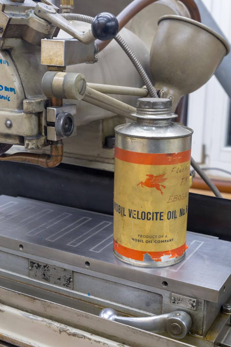
Back in the head, belt on and tensioned, wheel and dresser remounted. Dressed a wheel, fired it up.
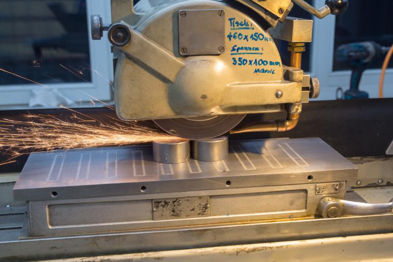
Just after midnight, the spindle ran, the hydraulics ran, and the wheel was true. Plenty of things still to sort out, but the machine was grinding.
The second grind#
A couple of days later I ran another piece, mostly to show somebody what the machine could do. The finish was noticeably better, and the only change was dressing the wheel more carefully.
One thing worth knowing about this machine: the cross feed is hydraulic and continuous, same as the longitudinal feed. For a finish pass the manual suggests running X and Y at similar speeds so the wheel tracks across the work at an angle rather than always parallel to itself. On that first grind I had a pink aluminium oxide around 46 grit dressed far too quickly.
The coolant system#
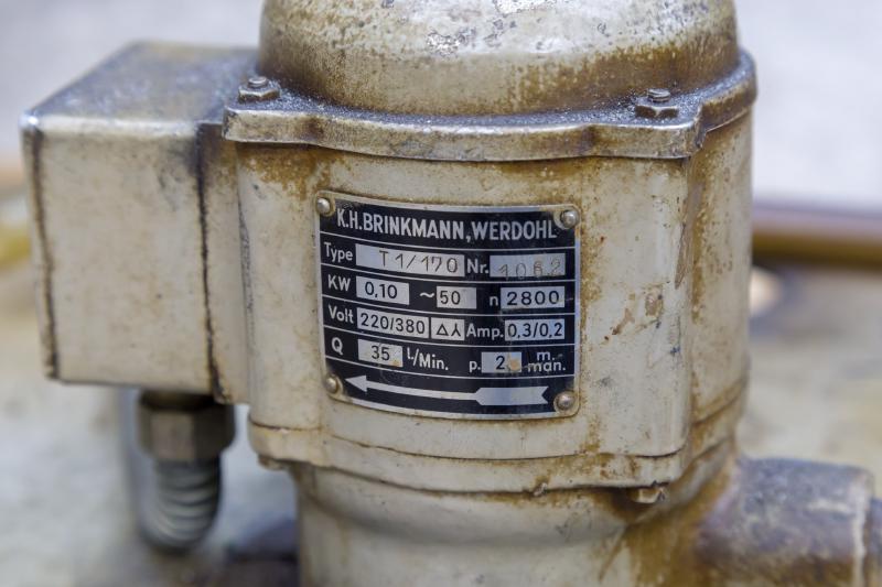
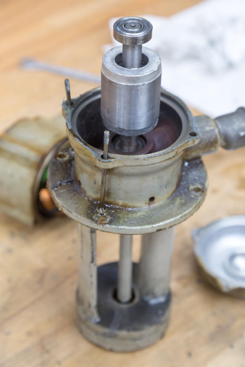
The coolant pump had been running but sounding rough, and the whole unit was heavily crusted. I stripped it down - pump and motor in one housing, which was standard practice for this kind of machine. Both bearings had long exceeded their useful life but a pair of standard 6001s would fix it. There is a purpose-built socket on the left skirt of the machine for the pump.
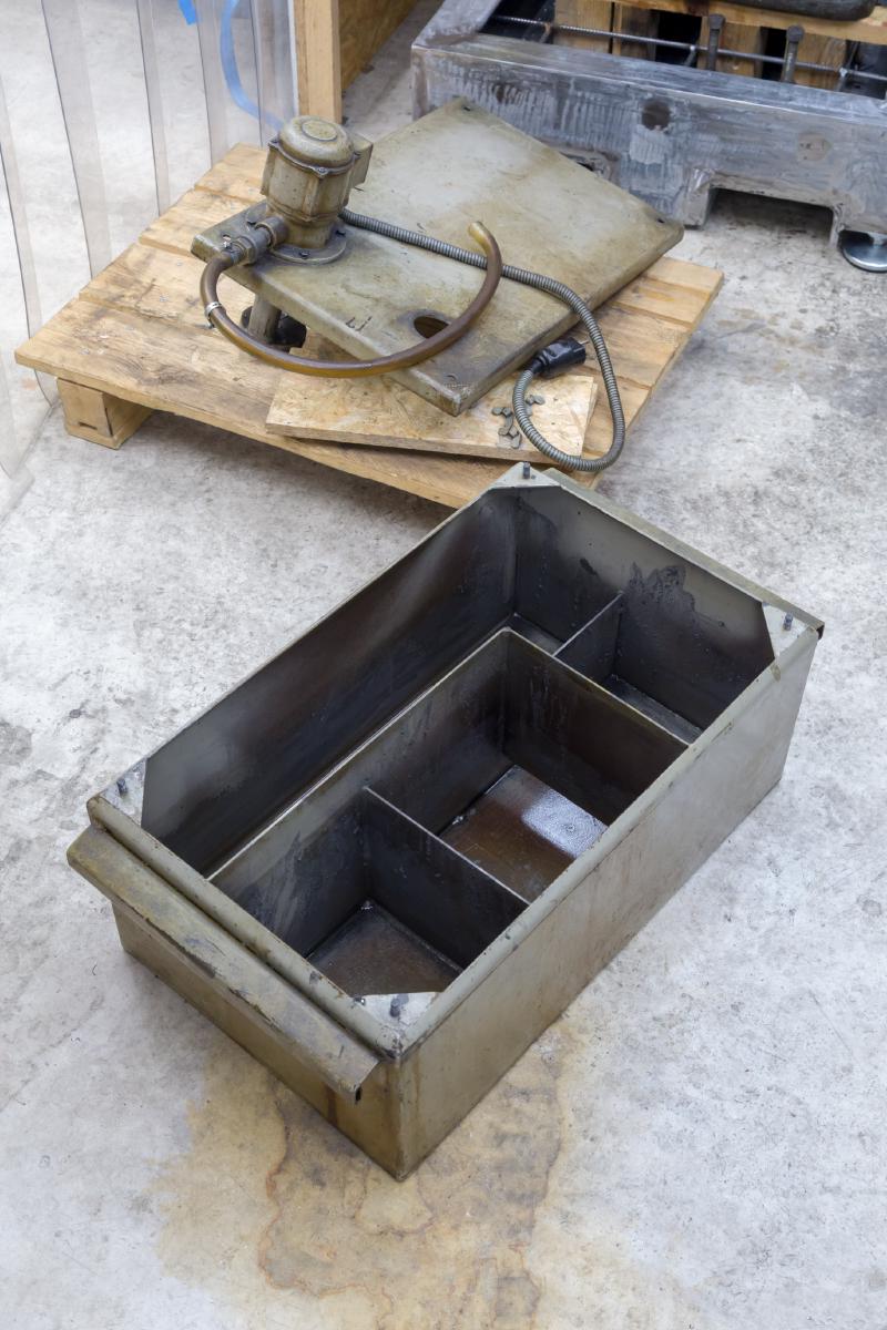
The coolant tank got a dose of oven cleaner, which worked well and left the paint intact. The hoses were perished and needed replacing.
The filter incident#
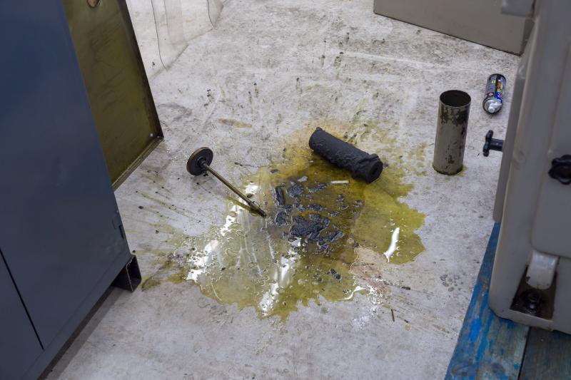
Then the filter. I lifted the lid carefully and moved the housing towards the waste drum.
The bottom fell out. All the grinding sludge and dirty oil went onto the floor. The rest of the evening was cleaning up.
With the electrics sorted, the spindle rebuilt, and the coolant pump out for new bearings, the quick work was done. The next step was a bigger teardown - table off, cross-slide out, and a proper look at the hydraulics.
Continue to Part 3: Table Off, Hydraulic Cylinders and a Z-axis Mishap.