Some of you may have seen my arduino-based inductance meter in this post: /posts/arduino-based-inductance-meter/. The guys at dangerousprototypes.com picked it up (http://dangerousprototypes.com/2014/12/16/arduino-based-inductance-meter/) and this blog got more visitors than I could ever have imagined. Thanks, dangerousprototypes.

The arduino-based meter works well and made a great proof-of-concept. But for everyday use you’re probabely not looking for an arduino solution but rather something that looks and feels more like a multimeter. That’s why I’m following up with this stand-alone version.
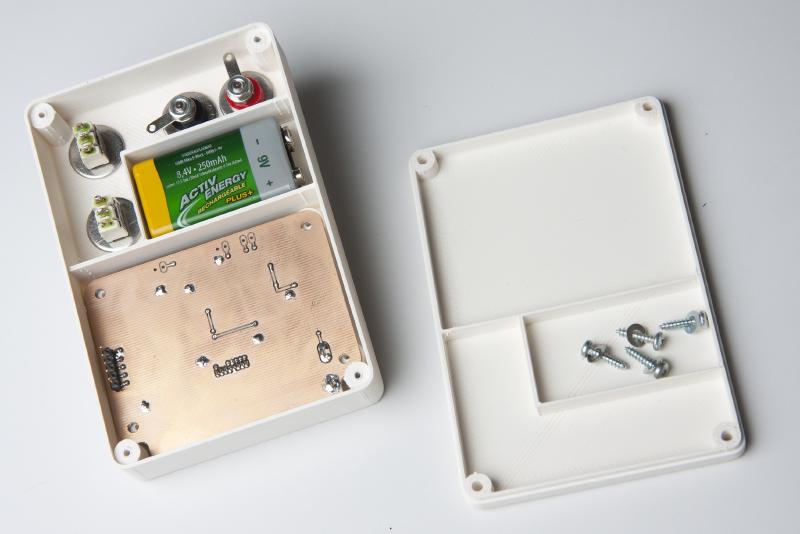
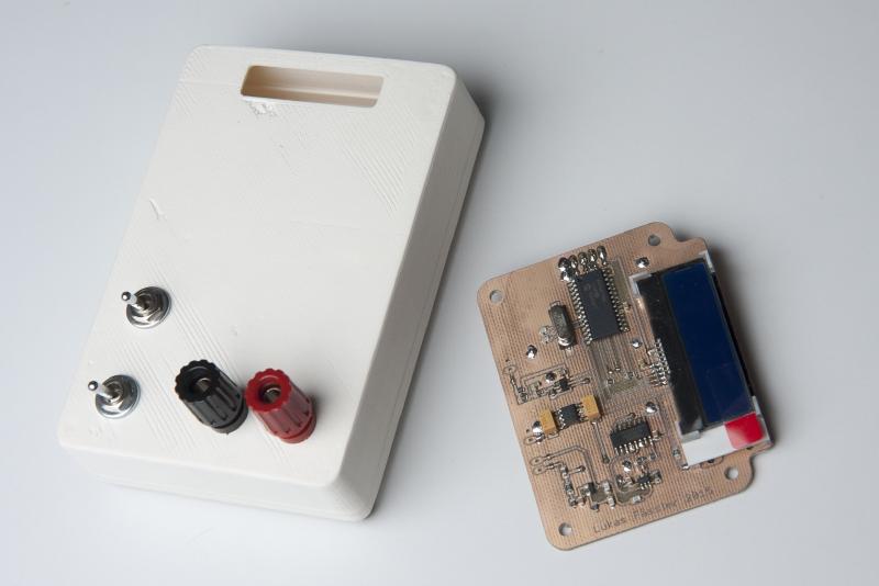
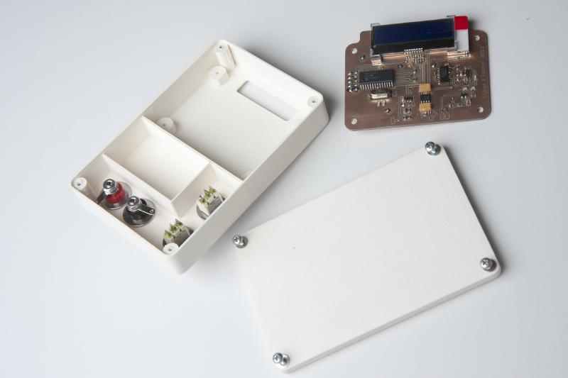
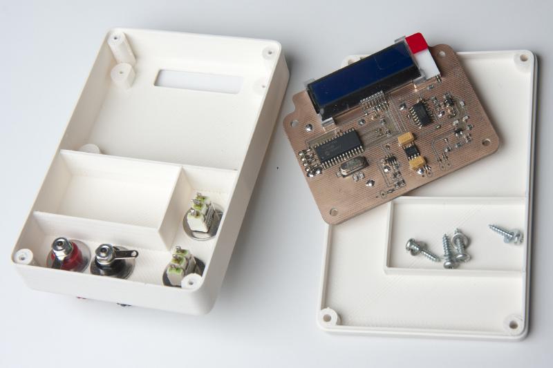
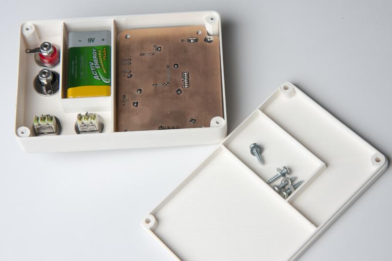
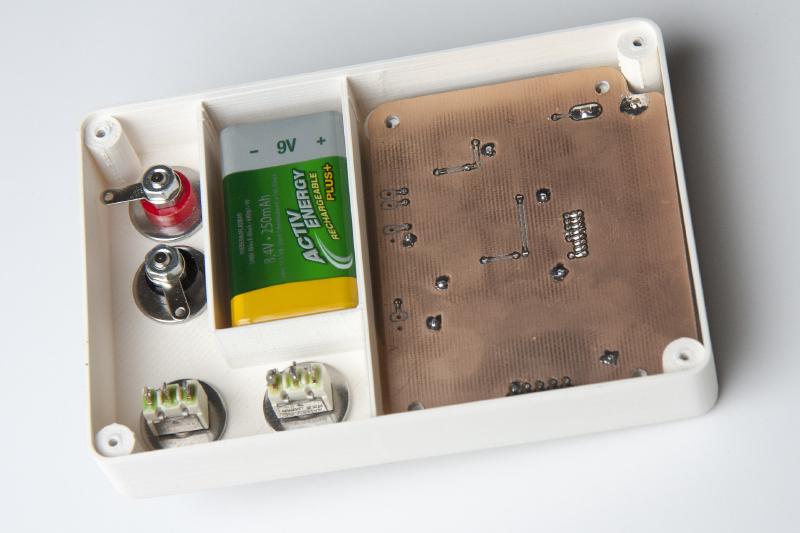
So this version is battery powered and comes complete with a 3D-printed case. It uses a mid-range PIC microcontroller, a PIC16F1936. Not that there’s much special about this model, I just happened to have some left from previous projects. I also thought about using a Atmel Atmega328, the same chip that is on the Arduino UNO.
Using an entirely different chip means I’ll have to write the software from scratch. But I felt that the Atmega328 was just too much of an overkill just to measure a frequency and control an LCD. They are quite a bit more expensive than the PIC, CHF 3.70 compared to CHF 1.90 @10pieces at Farnell where I get just about all my chips.

Talking of the LCD: The one I’m using here comes with a I2C interface. It’s blue with a white backlight and 2x16 characters and really tiny. I bought 2 of them years ago because they were small and relatively cheap (around 15CHF) and don’t require so many precious I/O pins of your microcontroller. Somehow I never used them but here their small size makes them a good choice. I/O pins aren’t a constraint here obviously as most of the 28 pins are unused.

I’m not yet familiar with the details of how they are controlled. I had a look at the data sheet and it looks like you send them just about the same commands like with the standard Hitachi compatible ones, just over I2C. But I expect to spend an evening or two figuring out the details.
The case was designed using FreeCAD. As the name suggest, it’s a free (and open-source) CAD design tool. This was only the second time I was using it but I found it quite easy to learn.
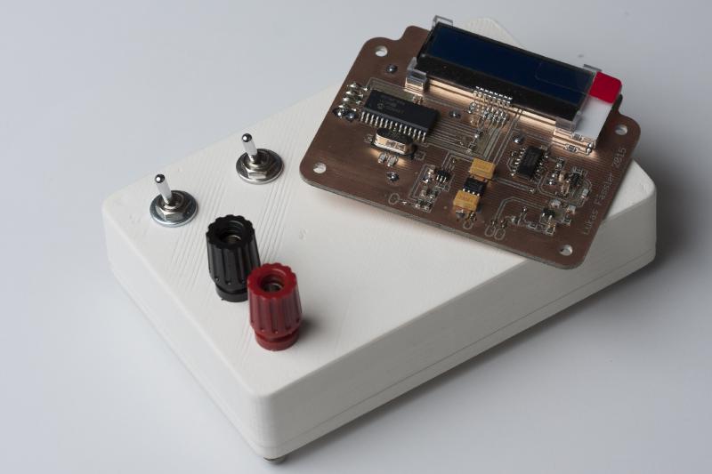
I printed the case at the Zürich fab lab (zurich.fablab.ch) on one of their Ultimakers. Was my first 3D-printing project, thank you very much for your support, everyone.
As always, I’ll put all the files online as a zip. So you can download all the Eagles plus PDFs as well as the FreeCAD models. Here it is: InductanceMeter (file no longer available). I haven’t written any software yet but I’ll but that online, too, as soon as it’s finished.
The software is ready now. Klick here for the next post: /posts/stand-alone-incuctance-meter-finished/.