It’s been way too long since the last post in my Ultrasonic Anemometer series. But better late then never.
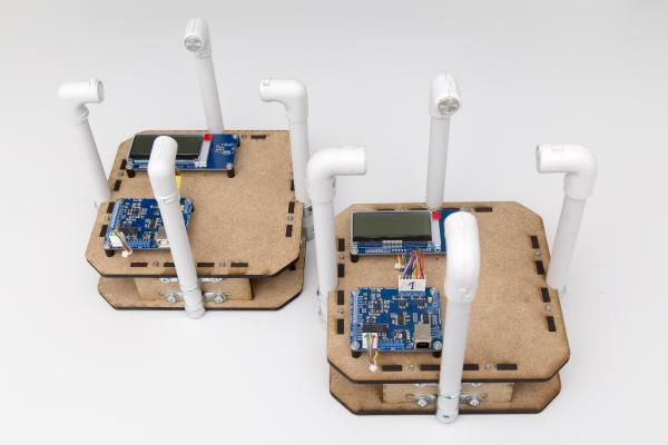
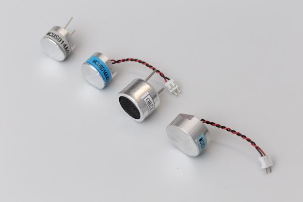
So far I have always used the same type of transducers. When I started this project I looked around and found the Multicomp MCUSD16A40S12RO. They were comparatively cheap and readily available so I ordered some and used nothing else for the next two or so years.
This will be my shortest post ever. But I just spotted a project on indiegogo.com that I think is worth mentioning: A small and affordable tool to do reflow soldering. It’s basically a heating plate specifically designed for reflow soldering. So it can reproduce JEDEC temperature profiles, it does data logging and and you can even control it via a web interface if you spend an extra 9$ on the wifi upgrade.
It’s time to follow up on the MPPT Solar Charger project. Progress has been slow since I’m currently working full time and doing a master’s degree at the same time. Given that this blog has previously been something close to a 50% job at times things will necessarily slow down a bit. But all the projects, including this one and the ultrasonic anemometer are alive and well and I’m working on them whenever I find some time.
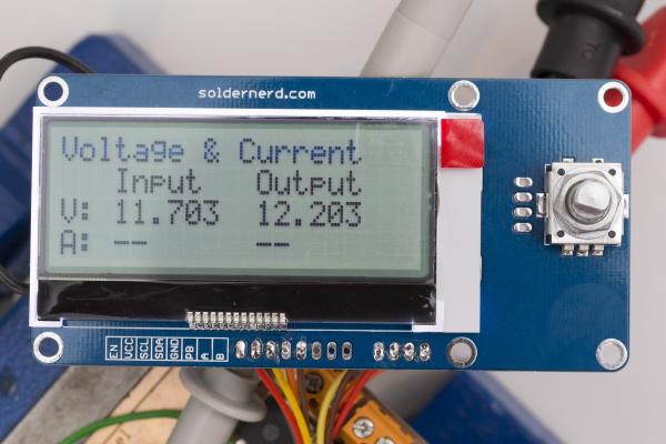
As you may have noticed I’m quite busy working on the MPPT Solar Charger project. The latest version uses a 4 lines x 20 characters LCD that connects via I2C as well as a rotary encoder with a push button.
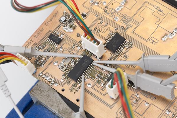
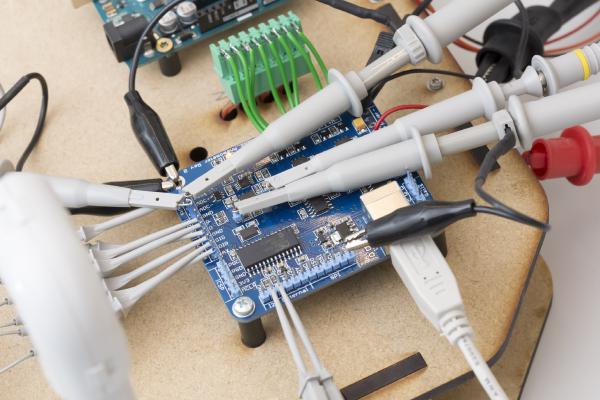
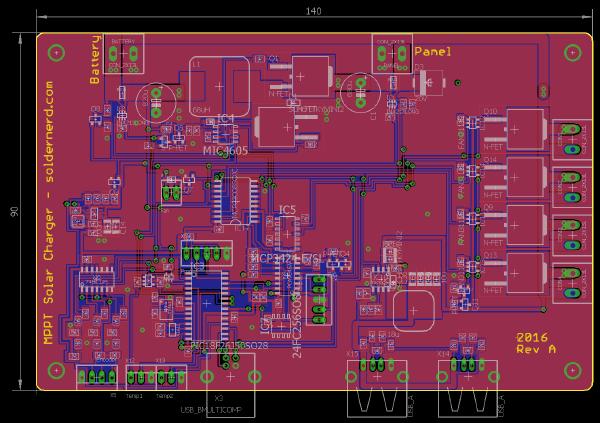
In a previous post I have presented a design for an MPPT Solar Charger. In the mean time I have built a prototype and also wrote some software for it. So today I’ll go through my findings of what works well and what needs to be improved. And yes, there are some flaws in the design…
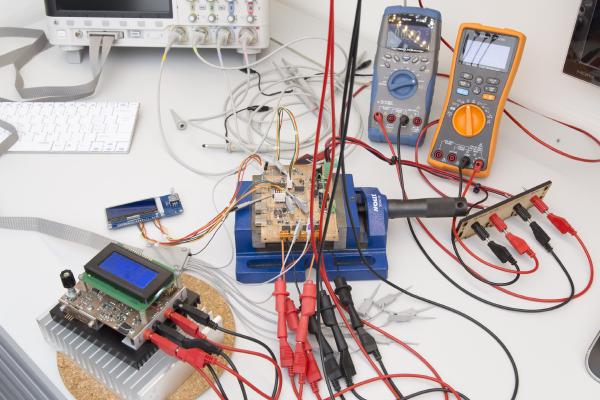
I last time proudly presented the new RevB board and got a lot of feedback from people who want one, too. As mentioned I have all the components here to ship up to 10 kits but I was reluctant to send anything until I had the chance to do some hardware testing. Not much had changed since the last revision but I don’t like taking chances on things like this.
Good news: the boards from dirtypcbs.com have arrived and look great. I also got all the components for the 11 boards. Why 11? I ordered about 10 (they call it a protopack) and was lucky enough to get 11. Thats dirtypcbs.
I’m currently waiting for the boards for my Ultrasonic Anemometer Rev B to arrive from Hong Kong and this gives me some time to write about the MPPT Solar Charger design that I did quite some time ago. I published a series of posts on a Arduino MPPT Solar Charger Shield and got a lot of encouraging feedback. But that shield was more of a proof-of-concept than a finished product. While it generally performed well it drew way too much current when idle to actually be deployed unless you can count on plenty of sunshine every day.