This is the first of a series of posts to follow. I will describe my attempts to build an ultrasonic wind meter (anemometer) based on an Arduino Uno. By the time of writing, I have a working prototype but it will take me a while to catch up in this blog. So this is just the first post - more will follow soon.
Click here for an overview over this series of posts on the anemometer project: /projects/arduino-ultrasonic-anemometer//.
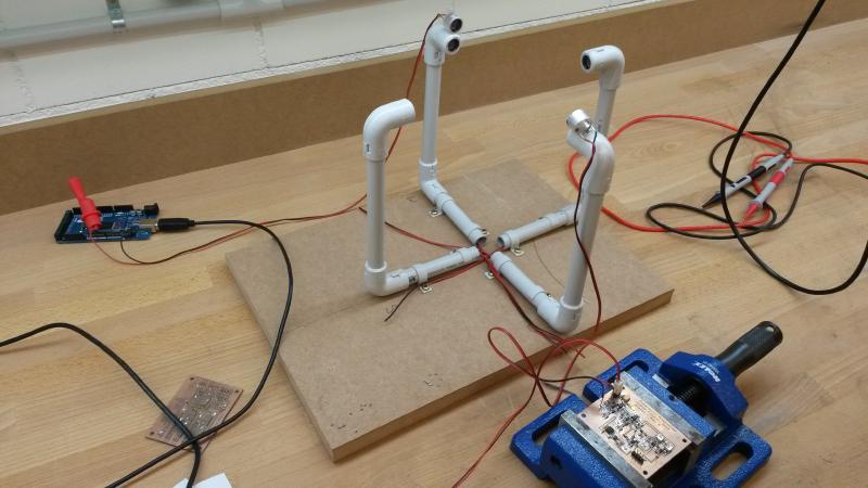
Let me quickly outline the project: My aim is to build an ultrasonic anemometer based on a Arduino Uno board. Now what’s an anemometer? That’s just a fancy name for a wind meter. I want to be able to measure both wind speed and wind direction with high accuracy. Most wind meters are of the cup or vane variety. They turn wind into mechanical motion and then measure that motion to calculate wind speed and possibly direction. An ultrasonic anemometer on the other hand sends and receives ultrasonic pulses and measures the time-of-flight. From the time-of-flight (or the time difference, depending on your approach) you can then calculate the wind speed in a given direction. Add a second pair of senders and receivers at a 90-degree angle and you get both wind speed and direction. As so often, wikipedia gives a nice overview/introduction to the subject: http://en.wikipedia.org/wiki/Anemometer
Surprisingly, there seem to be very few people out there who have done this before. Basically, there is this one brave guy named Carl who has built such an anemometer from scratch and put all the relevant infomation online.His project was published on hackaday.com and this is where I found it: http://hackaday.com/2013/08/21/ultrasonic-anemometer-for-an-absurdly-accurate-weather-station/. All of his documentation used to be at mysudoku.googlecode.com/files/UltrasonicAnemometer.zip (link no longer available — Google Code was retired in 2016). This material makes for an excellent starting point if you want to build your own. I’ve looked carefully at Carl’s schematics and have copied many of his ideas. I did end up changing quite a few things and will explain my reasons for doing so but the general approach is very much the same. Many thanks for sharing this with us, Carl.
The basic idea is simple: You send a ultrasonic pulse and measure the time until it arrives at a receiver located in some distance. Ultrasonic transducers often operate at 40kHz and so do mine. A transducer is a device capable of both sending and receiving a signal. It’s the kind of thing cars uses for their parking aids, telling you if there is an obstacle and at what distance.
In a 2-dimensional anemometer such as here, you will have 2 pairs of transducers for a total of 4. Let’s call them North, South, East and West for simplicity. You need to be able to send and receive pulses in all 4 directions: N->S, S->N, E->W and W->E. Not all at the same time but one after the other.
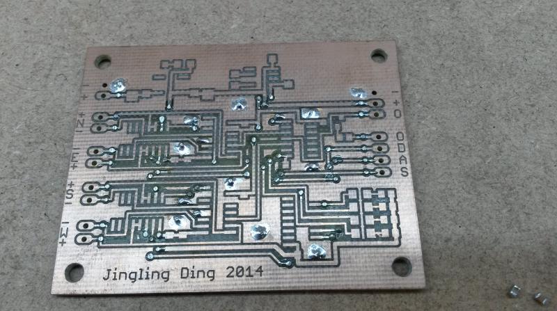
So you will need some kind of circuit to route your signals from and to any of the transducers. For example you want to send from the West transducers and receive from your East transducer or vice versa. Let’s call it the digital part even though the received signal is analog in nature. The PCB without components just above is the basis for this digital part. If you wonder who or what Jingling Ding is: That’s the name of my step daughter who helped me drawing and laying out this PCB in Eagle.
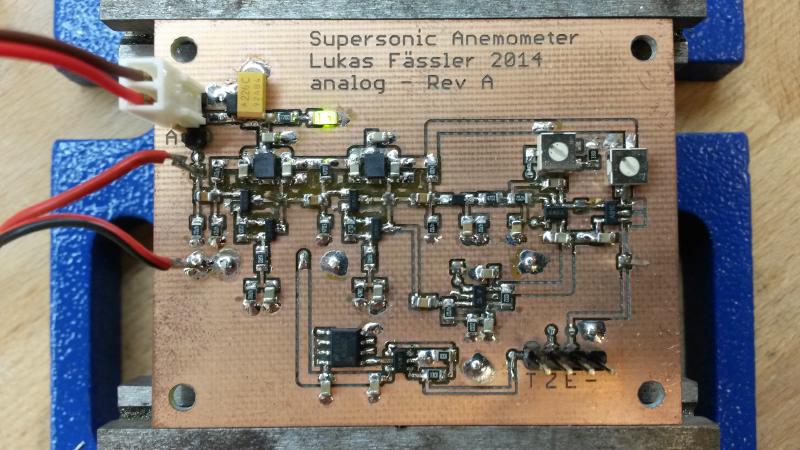
You will then need some more circuitry to process the received signal. This circuit is shared among the 4 transducers so only one can be listening at any point in time. That’s why the digital part needs to route the signal from the correct transducer to this signal processing circuit. The received signal is analog in nature and will be very weak compared to the transmitted one. So you will need quite a bit of amplification first. But this analog signal cannot directly be used by your arduino to measure the time of flight. You need some digital signal(s) that you can measure using the timer(s) on the arduino’s Atmega328 chip (in case of the Arduino Uno). Let’s call this the analog part. That’s what’s shown on the photo at the top of this page.
In my next post I will go through the details of the two circuits. Click here for the second post: /posts/arduino-ultrasonic-anemometer-part-2-digital-circuit/