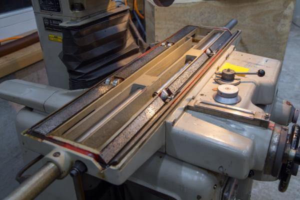
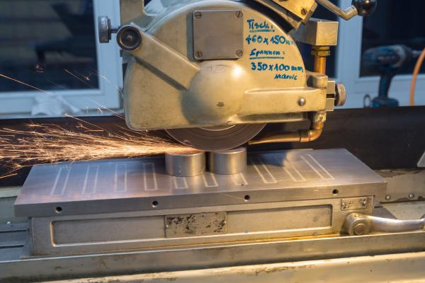
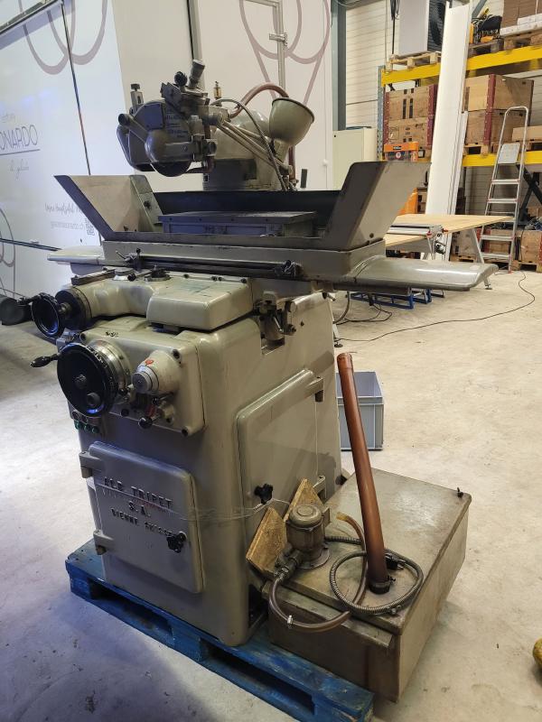
Part 3 of my Tripet MHP 500 restoration series. In Part 2 I got the electrics sorted and the spindle rebuilt. This time it was table off, cross-slide out, and a proper look at what’s underneath. Overview page: /projects/tripet-mhp-500/.
Part 2 of my Tripet MHP 500 restoration series. In Part 1 I picked up the machine and got as far as tripping the RCD on first power-on. The overview for the series is at /projects/tripet-mhp-500/.
This is the first of a series of probably four posts about the restoration of a Tripet MHP 500 surface grinder. The series came together a bit on the fly so the writeup is lagging behind the actual work. Everything shown here is already done and the machine is up and running.
This will be my shortest post ever. But I just spotted a project on indiegogo.com that I think is worth mentioning: A small and affordable tool to do reflow soldering. It’s basically a heating plate specifically designed for reflow soldering. So it can reproduce JEDEC temperature profiles, it does data logging and and you can even control it via a web interface if you spend an extra 9$ on the wifi upgrade.
It’s been almost three weeks since my last post and some further progress has been made. I’ve upgraded the microcontroller and can now control the gain of the second amplifier stage in software. But let’s look at the changes in some more detail.
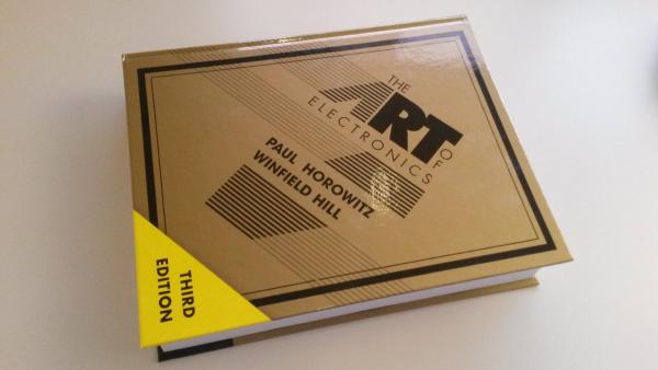
The world has been waiting since 1989, now it’s finally here. The 3rd edition of the classic book The Art of Electronics by Paul Horowitz and Winfield Hill is finally out. My (Amazon.de pre-ordered) copy just arrived today.
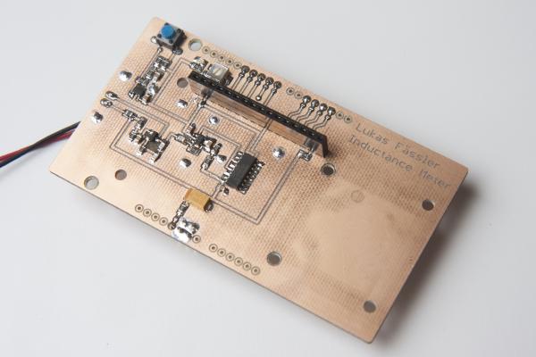
Incuctance meter in action. It displays the resonance frequency together with the inductance I’ve just finished a little Arduino project. It’s a shield for the Arduino Uno that lets you measure inductance. This is a functionality that I found missing in just about any digital multi meter. Yes, there are specialized LCR meters that let you measure inductance but they typically won’t measure voltages or currents. So I had to build my inductance meter myself.
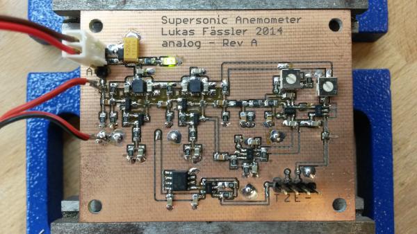
This is the first of a series of posts to follow. I will describe my attempts to build an ultrasonic wind meter (anemometer) based on an Arduino Uno. By the time of writing, I have a working prototype but it will take me a while to catch up in this blog. So this is just the first post - more will follow soon.
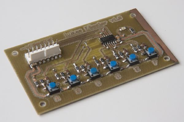
This was one of the first PCBs I ever made myself as well my very first attempt at soldering SMD components. So if you were wondering why some of the copper on the right has not been removed - that’s why. At that time, I was not even using Eagle yet but some software called Sprint Layout. But this post is not really about this unimpressing board but about proper debouncing. Something I feel strongly about ;-)
I regularly use PIC microcontrollers. I’ve tried some Atmel chips lately but I’m still by far most familiar with the PIC16 & PIC18 chip families. As you can see in my other posts, I tend to use SMD components but once in a while I need to program a DIP package.