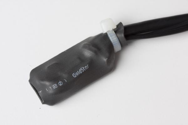
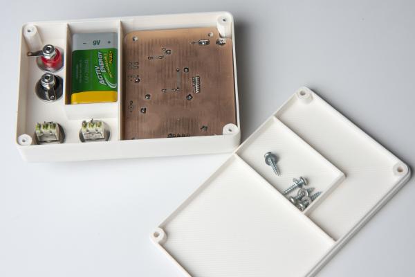
Finished 5V to 12V USB boost converter I frequently need a low-power supply to run a microcontroller system. Typically, one uses a lab power for such purposes. But at least on the desk where I do the programming I don’t have one. Since these systems typically consume little current it would be handy to be able to power them from USB. Most of my devices have on-board regulators so the voltage is rather uncritical. For 3.3 volt devices, the 5V from USB is just right. But others have a 5V regulator so they need a higher supply voltage. And even others might even need 12 volts.
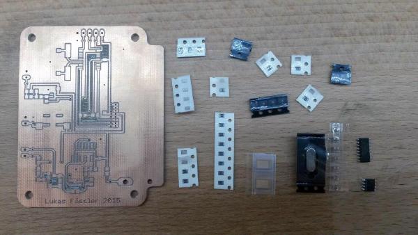
In a recent post I’ve offered a free PCB on a first-come first-served basis. I’ll be happy to mail the board together with some components to Mumbai, India tomorrow. It goes to Parth Sane, a student, homebrewer and soon-to-be ham radio operator.
It’s been a while since I posted the last update on the anemometer project. The reason for this is that I’m struggling with the aerodynamical design.
By the way: Click here for an overview over the ultrasonic anemometer project: /projects/arduino-ultrasonic-anemometer/
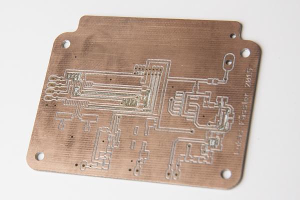
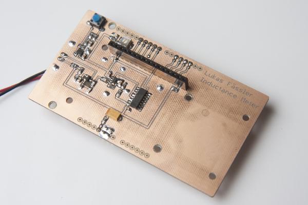
When I made the PCB for the stand-alone inductance meter, I erroneously used a SSOP footprint for the microcontroller (instead of the desired SOIC). The PIC is available in a SSOP package (PIC16F1963-I/SS instead of PIC16F1936-I/SO) but I didn’t have any at hand so I simply made a new board with a SOIC footprint.
If you’ve read my last post you’re already familiar with my Inductance Meter project: /posts/stand-alone-inductance-meter/. At that time the hardware was ready but there was no software yet. That’s been corrected, the inductance meter is now fully functional.
Some of you may have seen my arduino-based inductance meter in this post: /posts/arduino-based-inductance-meter/. The guys at dangerousprototypes.com picked it up (http://dangerousprototypes.com/2014/12/16/arduino-based-inductance-meter/) and this blog got more visitors than I could ever have imagined. Thanks, dangerousprototypes.
It’s been a while since the last post of this series. As so often, the task turned out to be more demanding than I first thought. And then I was also entirely new to assembly language, got distracted by my Inductance Meter Project (/posts/arduino-based-inductance-meter/) and went on a skiing holiday. But finally, the promised library is ready.
Incuctance meter in action. It displays the resonance frequency together with the inductance I’ve just finished a little Arduino project. It’s a shield for the Arduino Uno that lets you measure inductance. This is a functionality that I found missing in just about any digital multi meter. Yes, there are specialized LCR meters that let you measure inductance but they typically won’t measure voltages or currents. So I had to build my inductance meter myself.
This is just a very brief update on what I’ve been working on the last few days. By now, this blog has caught up with where the project currently stands so the blog posts won’t be quite as frequent as they used to be. When I just started this series I had already worked on this my wind meter project for two months so I had plenty of material I only had to post.
Today I’ll go through each part of my new Arduino shield to see if it performs as expected.
If you’re new to my Arduino-based ultrasonic wind meter project, you might want to click here for an overview: /projects/arduino-ultrasonic-anemometer/