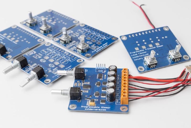
Around one and a half years ago I’ve designed and built various LED dimmers for both white and RGB LEDs. Then late last year someone approached me asking if I could make an RGB dimmer for him, too. But my designs were really tailored to their specific applications and built with home-made, i.e. milled PCBs which are time-consuming to make. So I decided to make a more universal version based on a proper, etched board which could be built in a small series and used for all kind of applications, both white and RGB. The result is this versatile, programmable 4-channel dimmer.
The design is based on my previous RGB dimmer but with a number of improvements.
soldernerd.com is now on YouTube
I’ve just uploaded a short video showing this device in action. Here’s the link: https://www.youtube.com/watch?v=ehZybd3Y2kc. This is only my second video so don’t expect miracles but I’d be interested to hear if you would like to see more videos in the future or if you prefer the traditional text and photos format.
Wide voltage range
It now operates from any voltage in the range of 6 to 26 volts as opposed to 12V only. In order to accomodate such a wide range of inupt voltages the regulated logic level voltage of 5V rather than the inupt voltage is now used to drive the mosfets.

Extremely low standby current
This 5V rail is generated by an LM2936 linear regulator with a very low quiscent current and shutdown input. That allows for a nice power saving feature for when all the outputs are off. After a few seconds of sitting idle the entire device powers itself off, i.e. it turns off the LM2936 thus only consuming 30 microamps (typ.) plus some leakage in the capacitors. So the device can stay connected to a battery for months without draining it. To wake it up one has to press any of the two push buttons.
Rotary encoder design options
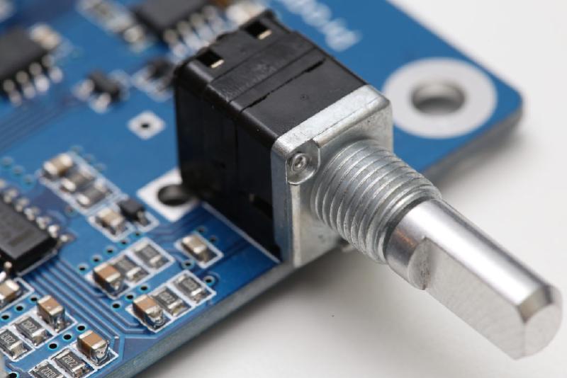
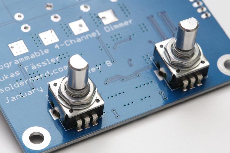
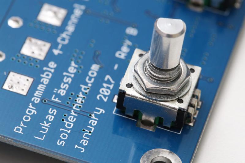
Talking of push buttons. Like my previous RGB dimmer it features two rotary encoders with push buttons.
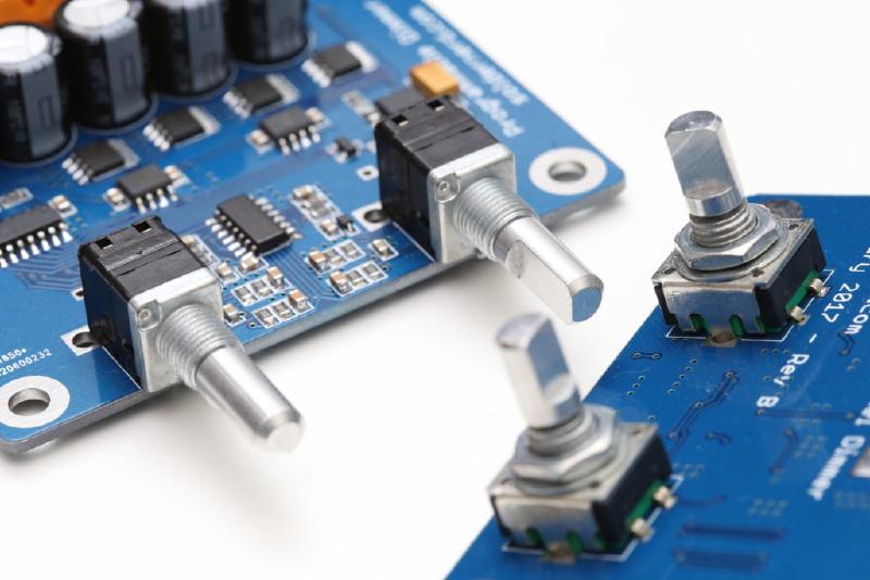
But now there are two different types of encoders that can be used. The ones previously used with their axis perpendicular to the board and a different type where the rotary axis is parallel to the board. And either type can be mounted on either side which gives you even more freedom for your physical design.

Perfectly debounced switch signals
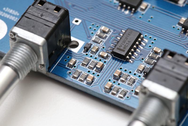
As always with my designs, the signals from the encoders (six in total) are nicely debounced in hardware by running the RC-filtered signal through a 74HC14 schmitt-triggered hex inverter. So the singals are perfectly clean when they reach the microcontroller.
Noise immunity
With my last design I had experienced some difficulties with ground bounce or insufficient ground connections in general leading to less-than-reliable encoder readings. It’s always more difficult go ensure good, low impedance ground connections on those prototype boards since there are no plated-through holes and vias. On that prototype board the issue was solved by soldering in a few short pieces of wire where the ground connection needed improvement.
So with this new design I paid very close attention to ground. I spent a lot of time working on the board layout to ensure that everything is as noise immune as possible. I always use ground vias generously but here I really tried everything to get the best, shortest and lowest impedence ground connections could get. I’ve also used decoupling capacitors even more lavishly than I usually do.
New microcontroller
I’ve changed the microcontroller to a PIC16F18325 which is smaller and cheaper than the previously used PIC16F1936. The 18325 has become my standard choicer whenever I need a low pin-count microcontroller. I particularly like its remappable pins which give a lot of freedom to simplify your signal routing on the PCB.
Smaller size and more outputs
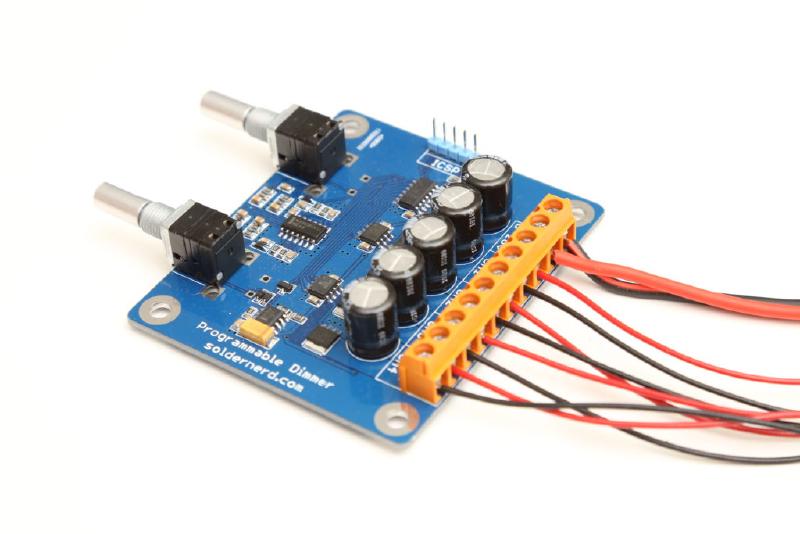
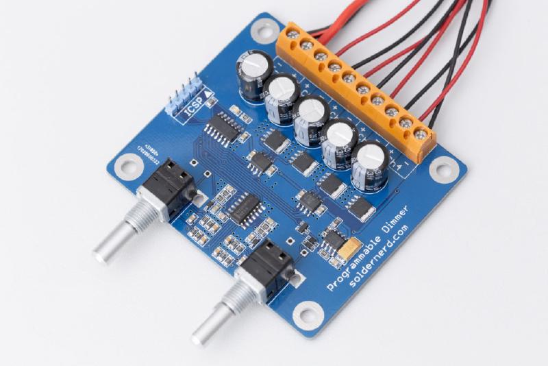
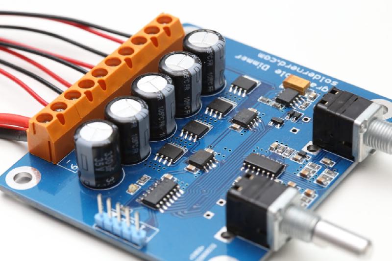
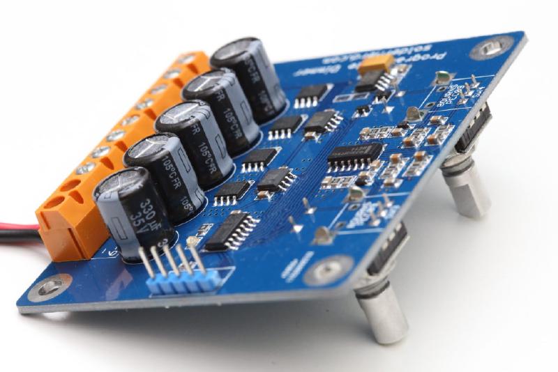
The mosfet drivers are basically the same as before but now with non-inverting outputs: LM5111-1M. There are two of them for a total of 4 outputs compared to only 3 with the previous version. They now drive much (physically) smaller but no less capable mosfets which allowed me to significantly downsize the whole board to 75x65mm. The NXP BUK9Y12-40E are rated at 40 volts and offer an on-resistance of 12 milliohms (max @ 25 degrees ) with a 5V drive as we have here. Their large thermal pads a the bottom (NXP calls that package LFPAK) pass heat efficiently to the PCB which then serves as a heat sink. There is also a 30V version that offers even better performance but with a maximum input voltage of 26 volts I thought the 40V version is the safer choice.
As you can see, there’s plenty of capacity on the board. A total of 5 330uF 35V low ESR capacitors are placed in parallel in order to smooth out the PWMs inherent current ripple.
Software
So now we have a device with 2 rotary encoders and 4 outputs but it won’t do anything without software. There’s absolutely nothing hard-wired between the encoders and the outputs so we can program this device to behave in any way we like. That’s what makes it so flexible.
I have so far implemented two functions. The first is aimed at RGB LEDs and behaves exactly like my RGB dimmer. One encoder controls the brightness, pressing its button turns the outputs on and off. The other encoder controls the color, pressing its button toggles between white and color. The three outputs are 120 degrees out-of-phase which presents a more steady load to the power supply.
The second function is aimed at plain white LEDs. There are two pairs of outputs with output 1 & 2 forming a group and 3 & 4 the other. Each pair is controlled by one encoder. Turn it to control the brightness and press its button to turn the respective output pair on and off. The two outputs of any group are 180 degrees out-of-phase to smoothen the load. And since there is a 4th output it is easy to implement a case where there is an independent white channel.
With both functions, the entire device turns off after a pre-defined period of time (currently set at 3000ms) with all outputs off in order to save power. Before turning its own power supply off and hence losing all its data in RAM, the necessary parameters are saved to EEPROM. So the device remembers its last state and will power up the with the same (brightness, color and so on) settings it powered off with.
The switching frequency is 31.25kHz which is high enough to be entirely inaudible and the 10bit resolution gives you 1023 levels to finely control the brightness down to very low levels.
All the settings reside in a file named config.h. That is where you define the function you want the device to perform. The number of brightness levels and their respective values can simply be parameterized there. The same is true for the colors. You can also set the RGB values for neutral white. The seemingly obvious choice of 1023/1023/1023 often does not result in a pleasent white. For my LEDs I had to substantially reduce the green content but this, of course, depends on your particular choice of LEDs.
I currently have 3 devices productively deployed and they perform very nicely. Also, adding new functions is easy since all the heavy lifting like has already been done. It takes somethign like 100 lines of relatively simple code to implement a new function. No need to get involved with any registers and the like. So if you have any experience in C you should be totally fine programming this thing.
Visit github for code and Eagle files
Both the eagle files (including Gerbers) and code are on github:
- https://github.com/soldernerd/DimmerHardware
- https://github.com/soldernerd/ProgrammableDimmer_Software
Also want one?
I have some boards left and can make one for you, too. Fully built, tested and programmed to your needs. Cost is USD 65 payable via PayPal, including worldwide shipping. Simply contact me using this form.