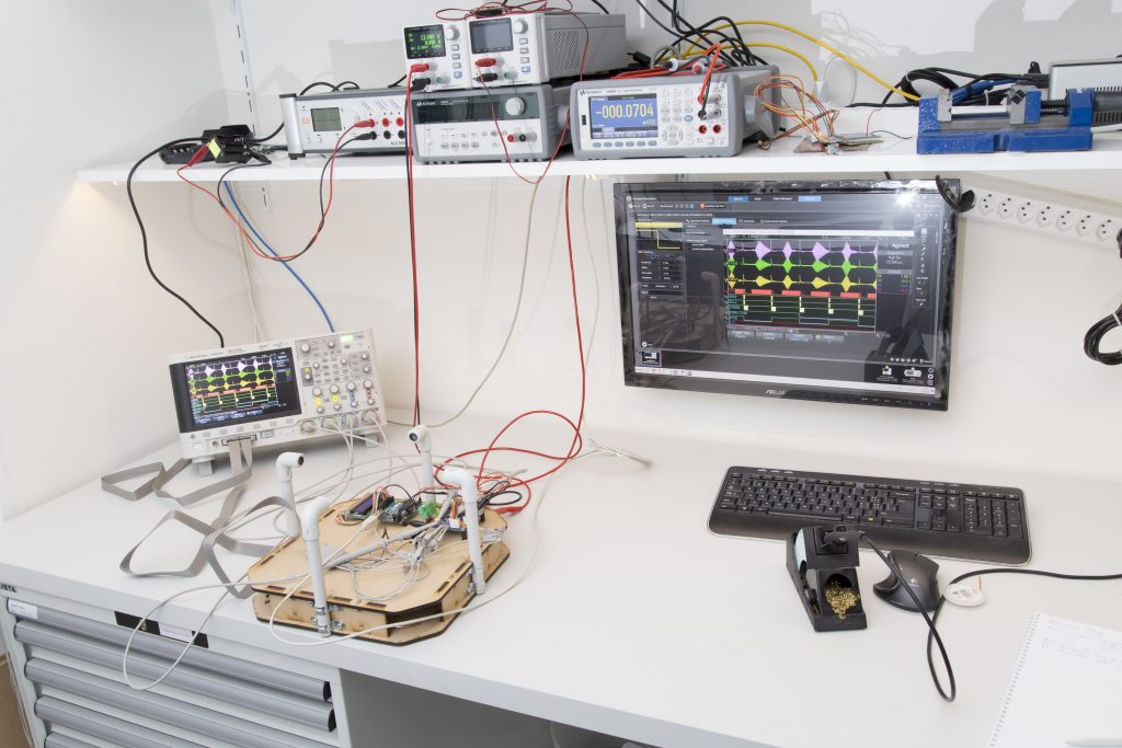
I last time proudly presented the new RevB board and got a lot of feedback from people who want one, too. As mentioned I have all the components here to ship up to 10 kits but I was reluctant to send anything until I had the chance to do some hardware testing. Not much had changed since the last revision but I don’t like taking chances on things like this.
In the mean time I managed to do some rudimentary testing and now feel confident to take orders. These tests concern the hardware only. What I said last time about the state of the software still applies. But let me tell you what I’ve been able to test so far.
Tests performed so far
- The PIC32 can be programmed from a PICKit3 via the ICSP header without any issues.
- Power consumption is as expected. Like the previous version it draws 45mA@12V (programmed) and the other two rails come up with +3.310 and -3.279V, respectively. Also as expected. Regulator stays cool.
- With the PIC controlling the AXIS, DIRECTION and SIGNAL pins, the transducers receive the 12V signal from the mosfet drivers. HOWEVER: the signals AXIS and DIRECTION are incorrectly labeled both in Eagle as well as on the silk screen. Electrically everything is fine but the names have been confused.
- The signal from the transducers is properly received (Rec pin on the board) and amplified by a factor of 11 by the first stage of the amplifier (S1 pin on the board).
- The PIC is able to control the digipot over the internal I2C bus and the second amplifier stage also performs as expected.
- The zero-crossing detector (ZCD) works.
- The input to the PIC’s ADC (ADC+ and ADC-) look fine, too. HOWEVER: the labeling on the silk screen is wrong. Eagle is correct, it’s just the silk screen. Plus should be minus and vice-versa. Again, electrically everything is fine.
- The PIC can communicate (as a slave) with an Arduino UNO connected to the external I2C bus.
- Communication over USB to a YAT-terminal under Win 7 works.
The following has not been tested so far
- For my tests I still used the transducers already used previously. I believe the ones I ordered last week are of the same type but I haven’t tested them.
- EEPROM. I haven’t tried the newly added memory yet. I have confirmed that it has power and is connected to the same bus as the digipot so I have no reasons to assume there are issues with it. But testing it would require some software first.
- The external SPI bus has never been tested, neither on the Rev A board nor with the new one. I don’t expect any problems but I haven’t done any testing so far.
Is there anything important that I forgot to mention? In that case just ask. A lot still needs to be done but at this point I’m confident that the board has no major flaws and performs much like the prototype. Want to give it a try? I have some kits left for you.
Continue here to the next post of this series.


I am ready to start soldering and testing my samples of the boards. Soldering iron is heated, the PIC3kit is attached to PC, software is installed, hope that will print on 3D printer my version of the box to mount the meter and transducers. So wait my kits. 🙂 Have a related question: Are the board mounting holes the same as on the Rev A version?
Please read `wait my kits` as ‘I am waiting the kits`.
Sorry for my bad English.
Great to hear. A total of 7 kits are on their way so there should be a nice small developer community soon. Very much looking forward.
Hey Lukas,
Amazing project! I’m working on a audio project that takes wind speed and direction to generate digital music.
I am interested in ordering.
Cheers
Alex
Hi Lukas and all,
do you have any feedback from the receipients of your kits?
Would be great to learn how this is proceeding!
Thank you for this great project!
Jimmy
Hi Jimmy
Yes I did get some feedback, mainly about some software tweeks individual users did to make the design work in their specific setup.
I also got a some suggestions of what (waterproof) transducers to use and I’m currently evaluating 4 different models in comparison. More on that soon.
Lukas
Have you tried piezo speakers? The ones with plastic membranes should be water-tight and the big membrane should be quite sensitive. Alternatively the 1,- € disc-shaped ones might work by glueing the piezo-side to the mounting pole.
Hi Lukas,
I was wondering what is hapenning after ZCD ? Once the signal feeds back to the Microcontroller, what sort of processing does it do ?
Regards
Hi,
is there a way to add a esp8285-01m for wlan connectivity and MQTT protocol? (https://www.seeedstudio.com/Seeedstudio-ESP8285-Wi-Fi-SoC-Module-p-2931.html)
Hi Renne
I lack any experience with this kind of module or protocol but I just looked at the specs and it seems to support both SPI and I2C so you can use one of those interfaces to connect to the anemometer.
Lukas
It’s a very cheap tiny Arduino with WLAN and flash storage. It’s the successor of the ESP8266. The MQTT-protocol is a very simple TCP-based protocol originally developed for Industrial automation. Meanwhile ESP8266 and MQTT have become the basis of DIY Home Automation.
Would it suffice to use ONE constantly transmitting ultrasonic transducer and TWO I2S-MEMS microphones in -120° and +120° angle to calculate windspeed and direction by triangulation of the accelaration and deceleration of the ultrasonic soundwave?
That could work if you knew the precise temperature. Usually you don’t so you need to measure in the opposite direction as well so that you have two equations and two unknowns, wind speed and temperature.
Also, I’m not sure how wide that transmitted beam is…