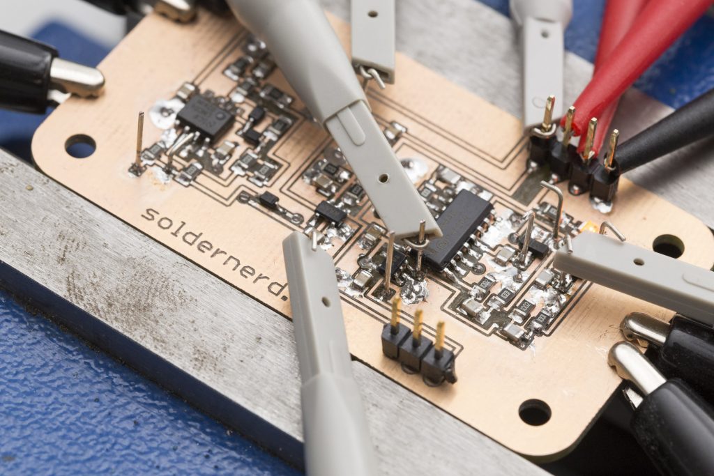
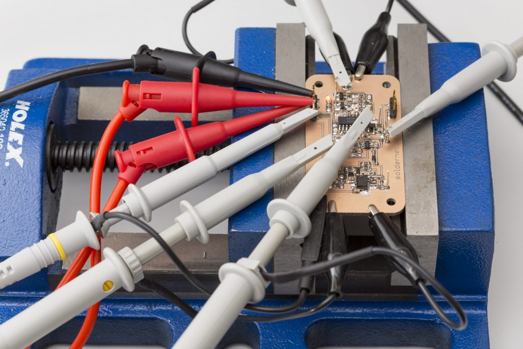
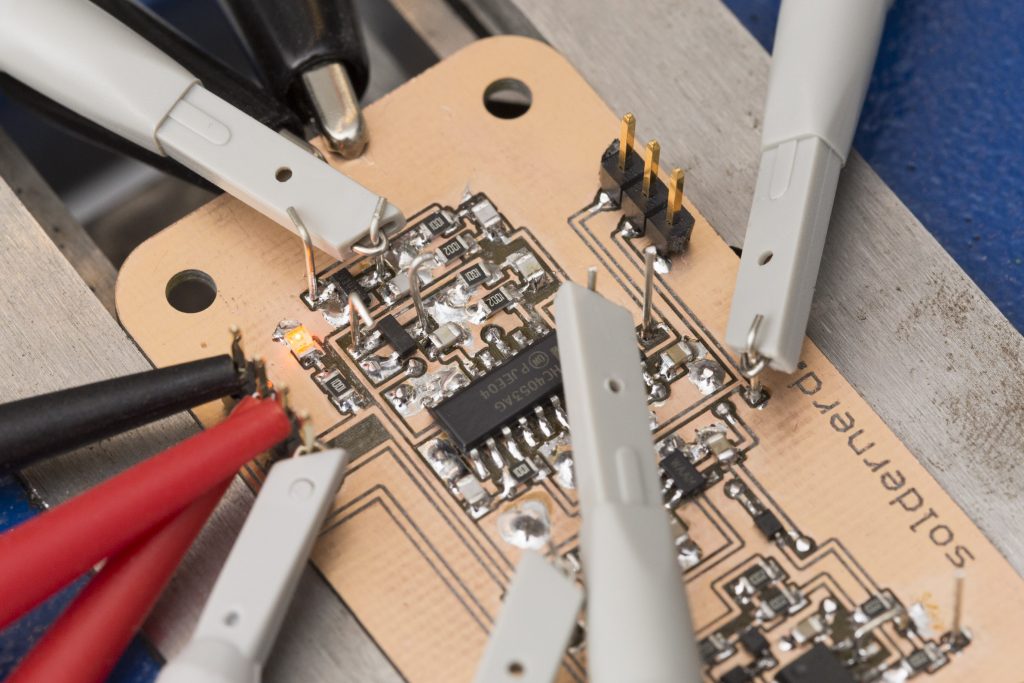
In my last post I went through the design of the analog part of the ultrasonic anemometer. Today we will see how the circuit designed last time performs in practice.
Active Full Wave Rectifier
Let’s first look at the active full-wave rectifier. As a first test I fed the input with a 40kHz sine wave from the scope’s signal generator. Here’s what I got to see on the scope.
The input signal is shown in yellow. The pink signal is calculated as the absolute value of the input and is what we are trying to archieve. Finally, the blue signal shows what we actually get on the rectifier’s output. What do you think? The basic wave form is obviously right but the precision leaves quite something to be desired. So I tried the same setup with an input signal 10 times slower, i.e. 4kHz.
As you can easily see, things look much better at 4kHz. That doesn’t make it much better for us since we need it to operate at 40kHz but there doesn’t seem to be anything fundamentally wrong with the design per-se. I think a faster op amp might be that is needed to make this thing work properly at 40kHz, too.
Zero-Crossing Detector
The zero-crossing detector is by far the simplest element of this circuit and has hardly changed since the Arduino anemometer shield. It’s output is shown in blue above. It works just as expected, no surprise here. Well, in the end it’s just a comparator so the sources for error are limited.
Peak Detector Sample And Hold
The input to the peak detector is the rectifier’s output so we should expect to see at least some inaccuracy carried over from the rectifier.
Below is what I got. Again, yellow is the 40kHz sine wave input. Blue and red are the peak detector of the positive and negative half-wave, respectively. Green is the output, i.e. either the blue or red singnal as chosen by the 2:1 multiplexer.
The good news is that the circuit basically works as designed. Each peak detector gets zeroed at just the right time. From the screen shot above one might even conclude that the peak detector is fairly accurate. Both half-waves show very similar amplitudes and the output is nicely held stable during the hold period. No droop is visible at least at this level of magnification.
Once you zoom in, things start to look less pretty. There is in deed no droop but the opposite. The output signal rises during the hold period. If you look closely in the screen shot above you can even see it – the segments of the green signal are slightly rising. We’re talking maybe 10mV here, far from dramatic but still.
Conclusion
My conclusion is as follows:
- Zero crossing detector: perfect
- Active rectifier: poor performance as is but can probably be fixed with a faster op-amp.
- Peak detector: ok but not good enough. might need lots of trial-and-error to improve it.
I have mentioned in a previous post that I’m still unsure if I should stick to the predominantly analog signal processing or if I should make the switch to a more contemporary, digital, DSP like approach. After having spent an evening or two testing and tweeking this circuit the answer became clear – go digital.
If you’ve followed my blog for even just a short while you have likely noticed that I enjoy designing and building hardware. Probably more than I enjoy writing software. But there are several good reasons to to more in software and less in hardware when it comes to this project.
- The circuit as described above works kind of. But it might take a loooong time to improve it until it really performs well. Chances are that it will never perform as well as I’d like it to.
- Board space. All this circuitry takes up considerable board space. A later version might use smaller components but this thing will always take up quite a bit of space – maybe a third of the total board area.
- Even with most of the heavy lifting done in hardware the Arduino is likely not fast enough. We’d need to sample the amplitude at 80kHz which is out of reach for the Arduino’s Atmega328 even when sacrificing some resolution.
- Further development. Chosing a digital approach enables users to actively contribute to the further development and improvement of this project.
- Versatility: Eqiping the anemometer with a dedicated microcontroller makes this project much more versatile. It no longer has to be Arduino specific. If you’re an Arduino lover I promise you it will always be Arduino compatible. No need to worry. But equiping it with a easy-to-use SPI or I2C interface makes it useful beyond the Arduino community.
- Cost. My analog design uses two op amps among other things. Precision op amps are relatively costly components. It’s not an expensive circuit but it will always cost several dollars for the components alone. And improving the circuit is unlikely to make it cheaper.
- Processing power is cheap. You might rightly say that a few bucks is not a lot of money to spend on some nice analog circuitry. I fully agree. But one can buy a lot of processing power for far less money nowadays.
Let me elaborate on some of these points:
Versatility: Arduino Only vs. Anyting, including Arduino
The arduino is a great platform with a great user community. But the Arduino Uno might not be the best choice for this project. A on board microcontroller gives user the option to use this anemometer from whatever platform they chose. Besides: An arduino is a very expensive device even when compared to a quite high-end microcontroller. 32-bit microcontrollers running at frequencies of 40MHz and higher are available for less than 2 or 3 dollars even in small (say, 10 pieces) quantities. More advanced models might cost, say, 5 dollars. In comparison, an Atmel Atmega328 as used on the Arduino currently costs CHF 3.10 (USD 3.18 at the time of writing) at Farnell. Not really value for money if you ask me.
Community Driven Developement
There are lots of creat coders out there. I can write decent code but there are plenty of people way better at that than I ever will be. I see this as an opportuinity to greatly improve this project. Once I get this thing up-and-running I’d like to build a small series and let users share their experience and contribute to the code. Have an idea on how it could be improved? Try it yourself if you have the skills. Share your code if it works. Or share your thoughts and ideas if writing emedded softwar is not for you. So the anemometer could get better and better without having to get new hardware. Just update the firmware.
Next steps
In the weeks to come I will work hard to find a suitable microcontroller and to design and build a board with all that is needed for a stand-alone ultrasonic anemometer.
It’s now ready, click here.


Hello from Slovakia again,
I just want to say big thank you for your effort with this project, you really made my day when I found out that you are continuing with development. I wanted to build arduino version of anemometer really bad, but I got stuck at finding right components and I can say I would not be able to perform all the magic with osciloscope and this kind of stuff.
So I am really looking forward to see some news and hope one day I will successfully build one of your designs.
best wishes , Lucas
Hi Lukas
Thank you for your very encouraging comment. I know I was not very active last year for personal reasons but I’m also excited to work on this project again. And I think it was a good idea to start from scratch again. I’m optimistic that I will have a new standalone board within a few weeks and once the hardware is finalized I will be happy to produce a small series so anyone interested can get one and contribute to the software development.
Hi there,
this is Jimmy from the US, looking for a solution, too.
Off the shelf units are way too expensive for our club.
Have you considered the Raspberry Pi 3 ?
$35 with all the power you’d need.
Also, please check out
http://www.dl1glh.de/ultraschall-anemometer.html#weiterentwicklung
He did a very thorough job (like you).
Hi Jimmy
What’s the application you have in mind? About the Raspberry Pi 3: Yes it definitely has a lot of power at a very reasonable price. The downside is that the RPi is running a fully featured operating system which means you get much less control over the actual hardware. For this project it’s crucial to be able to use microcontroller features such as timers.
So my solution was to put a more powerful microcontroller directly on my board. See my latest post for details: https://soldernerd.com/2016/05/11/ultrasonic-anemometer-part-20-standalone-anemometer-design/
regards
lukas
For those who still don’t want to “go digital”, here’s an idea for another analog peak detector if this one is inappropriate. We could use an op-amp differentiator circuit. Feed it directly with the amplified signal, the output will be zero when there is a peak. Then this ouput goes trough it’s own zero detector and there you have it. I never used that kind of circuit in pratice so there may be some dramatic issues requiring a lot of tweaking. And of course, if the LMC6482 op amp doesn’t do the trick with the full wave rectifier, it won’t here either probably, so this also needs a faster op amp. If the slew rate condition of the amplifier stage can’t be met here, it shouldn’t be a problem since the noise has already been filtered out. So a bigger slew rate wouldn’t pose a threat now, I suppose.