
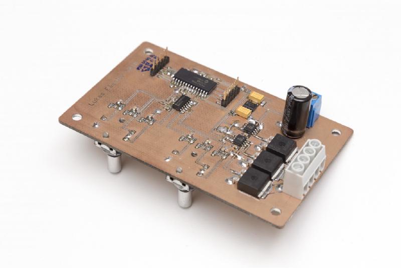
In my last post I’ve described the design and construction of my LED dimmer project. This project here is similar but a bit more involved. It controls RGB LEDs so it can not only change the brightness but also the color of the light. Instead of a simple pot it used a pair of rotary encoders with push buttons. One controls the brightness, pushing its button turns the light on or off. The other changes the color, pushing its button toggles between color and white.

There’s also a I2C interface included this time. I originally had the idea to hook this thing up to a Raspberry Pi and so be able to control the light from my computer or cell phone. I did establish an I2C connection to the RPi and it all works but it’s now installed as a stand-alone solution.
Since we’re now controlling RGB LEDs we obviously need three independant PWM outputs, one for each for red, green and blue. But let’s go through the circuit step by step.
Power Supply
The board is powered from a fairly powerful 12V supply that is always on. A LM2931 turns this into a microcontroller-friendly 5V. But if we want to connect this board to a Raspberry Pi we need to match the RPi’s 3.3 volts operating voltage. Apart from hobbyist projects there aren’t many microcontroller circuits running at 5V nowadays. Most of the PIC16Fxxx family of chips still handle 5 volts but this is becomming more and more of an exception. So in order to be compatible with the rest of the world this board will need a way to adapt it’s voltage.
What I’ve done here is the following: The board has it’s own 5V regulator and you can power from that using a jumper on the I2C header. On the other hand, if the board is connected to a Raspberry Pi over I2C, it will just freeride on the RPi’s 3.3V operating voltage. Since the board is only drawing a few milliamps at 3.3V this is perfectly fine. The RPi specs allow for 30mA or so to be drawn in this fashion.
Rotary Encoders
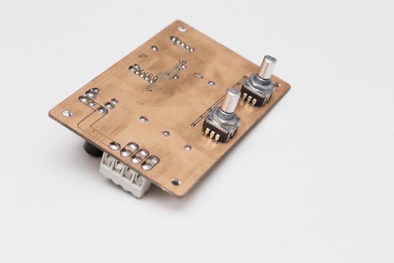
I’m using a pair of Bourns PEC11R-4215F-S0024. These are 24 steps-per-rotation encoders with a push button that I’ve used for other projects before. I’ve made it a habit to debounce switches and encoders in hardware rather than having to worry about it in software. There’s even an entire post just on that subject: https://soldernerd.com/2014/11/12/switch-debouncing-using-74hc14/.
So all 6 signals comming from the encoders are first RC filtered and then run through a 74HC14 schmitt-triggered inverter and reach the PIC nice and clean.
Microcontroller
I’ve once again used a PIC16F1936 but this is entirely uncritical since most microcontrollers come with the features needed here. We mainly need 3 10-bit PWM modules and an I2C interface if we want to connect to the Raspberry Pi.
The PIC is running at 32MHz using its internal oscillator which gives us a maximum (10-bit) PWM frequency of 31.25kHz which has proved adequate in my last dimmer project.
Output
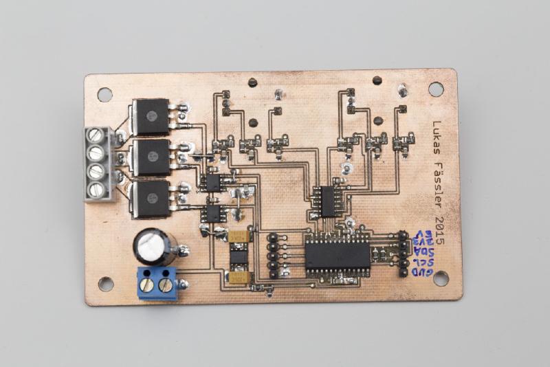
I once again used the inexpensive yet powerful Infineon IPB136N08N3 N-channel MOSFETs. Since I have to drive 3 of them this time I need two LM7111 dual MOSFET drivers. As opposed to last time when each output had its own capacitor, they now all share a 1.5mF electrolytic cap.
Software
As so often, most of the interesting stuff happens inside interrupt service routines (ISRs). This one serves two tasks:
- Read the input from the rotary encoders. Every time one of these input signals changes, an interrupt (interrupt-on-change, IOC) is triggered and the ISR calculates the updated values for brightness and color and sets an update flag so the main code knows that something has changed.
- Send and/or receive data over I2C. The PIC is configured as Slave so it won’t do anything unless some other device attached to it will request or transmit data. The ISR just technically handles the sending and receiving o data. It just fills a receive buffer or sends data from a send buffer. It is entirely up to the regular code what should be sent and how received data is interpreted.
As I’ve mentioned I’m not using the I2C interface at the moment so the implementation is somewhat basic. Data can be sent to the board and it is stored in a recieve buffer but nothing is not processed. When asked for data it transmits up to 11 bytes indicating it’s current state of operation such as brightness of each color channel and some more data.
There is also nothing preventing the content of the buffer from being changed while a transmission is in progress. So if you’re planning to really use this I2C feature you probably want to improve it somewhat but the code (download link at the end of this post) gives a good, working starting point. If you need help, just ask.
Controlling the outputs is not that challenging. Its jus 3 10bit PWM modules running 120 degrees out-of-phase to smoothen the current seen at the input. Again, the LM7111 I’ve used are of the inverting type so the duty cycle has to be inverted in software.
I’ve used a lookup table for brightness (only 32 brightness levels this time) and color. I’ve defined 24 colors that make a nice color circle. You can turn the color encoder infinitely and just loop through the colors defined in the lookup table. When you press the button on the encoder, the color changes to plain white but the color is remembered so when you press the button again the same color comes back. Brightness works in a similar way: press the button and the light goes off, press it again and the light is back with the same brightness as before. Overall, this makes a quite intuitive user interface.
Testing and Troubleshooting
Acoustic noise was not an issue this time. I started with 31.25kHz switching frequency and 120 degrees phase shift right away. Apart from that the power level is lower, more like 70 watts maximum. And I was using a different supply that might be less susceptible to acoustic noise. don’t know, haven’t tried.
Mass connections have proved to be a problem, though. Usually I take great care during board layout to make sure all components have excellent ground connections. Together with the generous use of 100nF ceramics decoupling capacitors this prevents lots of problems before they even appear. Thank you John Catsoulis (http://shop.oreilly.com/product/9780596007553.do) for stressing this point when I started designing my own circuits. You might have noticed that just about every IC on any of my designs has its own ceramic cap on each of its power supply pins. That’s thanks to John and it has served me very well.
But back to the problem: It seems that this time I’ve been a bit sloppy with my ground connections around the two MOSFET drivers and the encoder on the right. They’re not that bad but aparently not good enough. The LM7111 are quite powerful. Up to 5Amps peak current according to the datasheet. And together with my not-so-great ground connections that was enough to get false triggering from that encoder. A few wire bridges improving the ground connections solved that problem. I’ve already fixed that problem in Eagle so the files available for download should be fine.
There was also another problem: It was impossible to turn the green (middle) channel off entirely. No matter what I did in software, the green LEDs always stayed on if only a little bit. I looked at the PWM signal from the PIC on a scope and there was a slight glitch every full PWM period, aparently when the PWM register overflows from 1023 to 0. The other two channels (red and blue) didn’t suffer from this problem.
As I said, I have to correct for the inverting nature of the LM7111 in software. The enhanced (ECCP) PWM modules can do this automatically. But there are only two if them in a PIC16F1936 so I had to use a regular (CCP) module for the green channel. So in order to turn the green LEDs off the duty cycle has to be 100%. And that seems to be impossible without that little glitch.
I first tried a pull-up resistor on that PWM signal but that didn’t help. The pic seems to actively pull that pin low. So I resorted to a 10pF cap to ground which finally solved the problem.
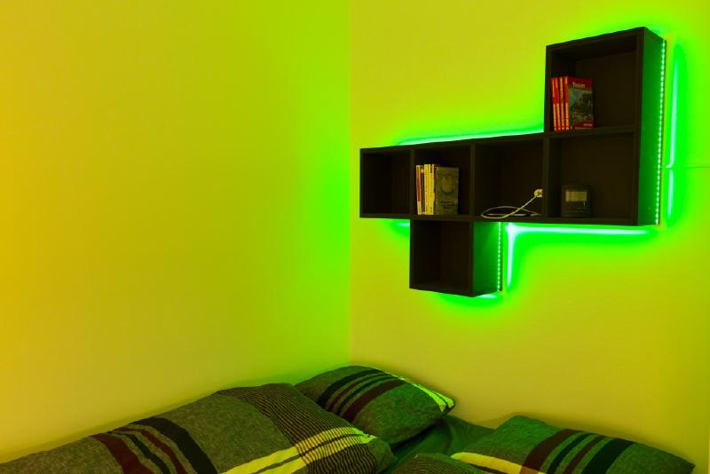
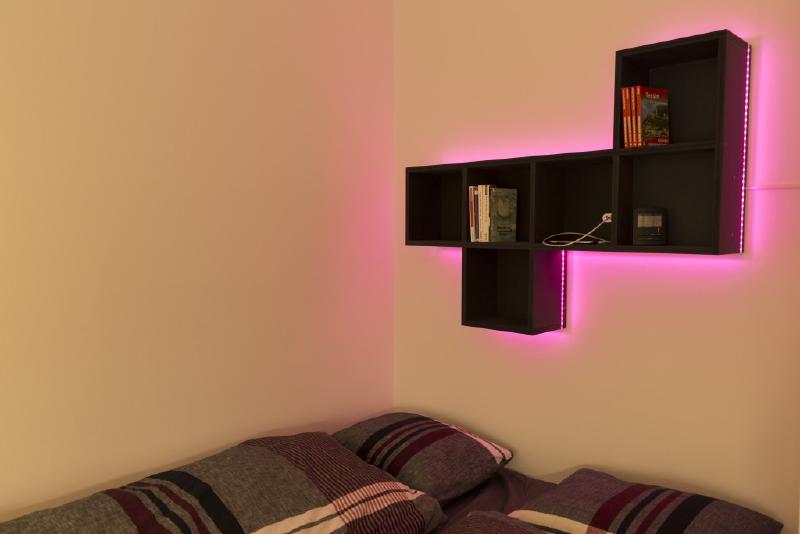
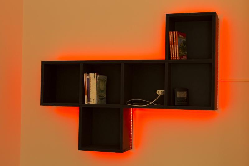
Since the board is installed hidden in some kind of bookshelf I didn’t make a new pretty board with all these fixes already in place. But I’ve now been using it for two months or so and it works perfectly every day.
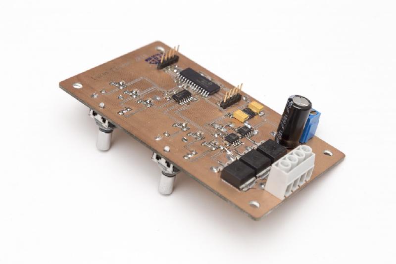
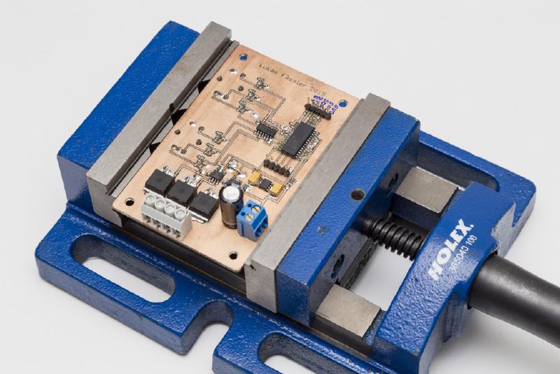
I’ll finish this post with a few impressions of the final product and the download link below.
As always, here you find the Eagle Files, PDFs of schematic and Board as well as the code.
Hi, I’m wondering if you would be willing to make one if these to order?
I’m converting a camper van and would love to have RGB lighting in the rear that I could easily control colour and light output with dials up front. Although I’m fairly handy, this is way beyond the limit of my expertise at the moment!
Thanks , Andy
Hi Andy
Thanks for your interest. So you would take the rotary encoders off-board and mount them at somewhere in the front? Or you put the entire unit in the front and run some power wires to the LEDs in the back? Well both seems quite doable but I’d probably go with the latter approach.
Making milled boards (as the one used here) to order is not really feasable because it just takes way too much time. These really are prototypes. But I could do a revised version and get some made at dirtypcbs.com. So the answer to your question very much depends on your timeframe. If you need the board within the next few weeks unfortunately no. But if you’re more aiming at the beginning of the camper season (say, April) then that’s well possible.
Regards
Lukas
Hi Lukas,
Option two sounds like he more feasible approach depending on how big the board would be. If you could give me an estimate for the cost I’d be happy to wait until April.
Regards, Andy
Hi Andy
I’ve done the redesign for the schematic but not the board yet. The Rev B will be considerably smaller, probably 75x65mm or so. It will have 4 outputs instead of 3 (some led strips have an independent white channel) and be able to run from any voltage in the 6-26V range. The board will also be much flatter (about 14mm without the encoders) since I use 5 smaller capacitors instead of one big one. The idea is also to implement an ultra-low power mode for when the board is connected to power but the lights are off. In that state the board will only consume a few microamps hopefully. No more I2C interface, though.
I will probably finish de design by end of January, then I will have the boards by end of Feb and will be ready to ship around end of March. I think this is realistic but no guarantee. I just went through the bill of materials and I’ll need 60$ for it, including worldwide shipping.
Regards
Lukas
Hi Lukas – I have been reading your posts, in particular trying to find a pretty solid way of debouncing rotary encoders and their push buttons for use with an Arduino. In one of your comments you said:
“I typically use a 1uF capacitor and, 10k for the pull-up resistors and 22k or 33k for the other resistor and that usually works just fine.
For a switch, anything similar to this should work so you can use components that you use in other parts of the circuit as well.
For rotary encoders I use the same resistor values but only a 100nF cap.”
When I looked at the schematic for this project you use (on the encoder) a 33nf cap, 10k pullup resistors and the other resistor is 10k also. On the push button you use 2 x 10k resistors and a 100nf cap in the RC filter.
In your “switch” demo project you use values of 2.2k for the pullup resistor and 5.1k for the RC filter resistor and a 3.3uF cap.
Have you changed your approach to hardware debouncing ? I am looking at using the Bourns 24 pulse rotary encoder (I think its the same one you use).
I am going to feed the output of the hex inverter into a Dual D Flip Flop IC (74HC74) to produce a step and direction pulse to be read by the arduino.
Any help would be appreciated !
Hi Brant
Thank you for your relevant question. I haven’t changed my approach to debouncing in general but yes, the component values have evolved over the years.
The first shift has been towards larger resistors and smaller caps, hence reducing current while keeping the time constants relatively unchanged (why use 2k2 & 3.3uF if you can use 22k and 330n with the same result…)
Later I have also started using less debouncing (less meaning shorter time constants). The bourns rotary encoder deliver relatively clean signals (little bouncing) and therefore only need little debouncing (but like all mechanical switches still need some).
Bourns recommends 10k / 10k / 10nF in their data sheet but I have found that a bit on the low side. In my later designs (like my latest dimmer or the user interface) I have always used 22k/10k/10n for the rotary encoder pins and 22k/10k/100n for the push button. That works very well for me.
Using a flip flop to decode the signal sounds interesting, I’ve never done it. Do you maybe have a link to share?
Cheers
Lukas
Thanks for the reply ! I’ll start with your RC resistor / capacitor values and see how I go. Look at this page for the explanation on the Dual Flip-Flop. I am going to use the same logic but use the 74HC14 Schmitt inverter and the 74HC74 Dual Flip-Flop.
http://www.bristolwatch.com/ele2/rotary.htm
“We use a CD4013 D Flip-Flop that operates as follows: If B is HIGH on pin 5 when A goes from LOW to HIGH on pin 3 the Q output on pin 1 goes HIGH and is stored there. By reading that single bit we know direction say CW.
If the shaft is rotated in the opposite direction B is a LOW on pin 5 is stored on Q when A on pin 3 goes LOW to HIGH. Now we know the shaft was turned in the opposite direction (CCW) when Q is polled by a micro-controller.
In addition Arduino or PIC can poll STEP as a count pulse in addition change in direction on DIR.”
So you can use the clock input as a step pulse and the dir output to sense direction with no need to decode via an ISR, on the 74HC74 I can just poll PIN3 for the step and PIN5 for the direction in the main loop.
When you say:
” I have always used 22k/10k/10n for the rotary encoder pins and 22k/10k/100n for the push button. That works very well for me.”
Are you using the 10k resistor as the pull up resistor and the 22k/100n for the RC section ? I tried this on a cheap rotary encoder I had and had many false readings – still waiting for my Bourns rotary encoders to arrive.
Hi Brant.
Precisely. This way the capacitor is charged via 10k+22k=32k and discharged via the 22k. So the time constants between charging and discharging are similar.
As I said, the these encoders produce relatively clean signals with little bounce. Some models (including the more expensive Alps I’ve used before) were significantly worse.
Also: many encoders produce two transitions between two dents so you can chose which one to trigger on. In my experience, one (usually the second one in that direction) performs quite a bit better than the other.
If you have the possiblity of looking at the signals on a scope – do so. It often helps a great deal in understanding the problem and if more or less debouncing is needed.
Lukas
Ok that makes sense ! One last question… On a couple of the hundreds of pages I have read on this topic people have referenced possible contact damage in the encoder switch contacts as the capacitor discharges to ground. I cant find the page but some someone said a FET on that outbound path would resolve the issue. I am wondering if a simple NPN transistor would suffice to allow the current to discharge to ground through its collector and emitter rather than the current going via the encoder contacts.
Actually – I may have got that around the wrong way. Maybe using the rotary encoder output to switch the FET / transistor. The RC circuit would then discharge via the FET / transistor junction as opposed to going via the encoder switch contacts.
Hi Brant
I’ve seen circuits where people just used a pull-up resistor and a cap accross the switch. So no RC filter but just the cap to filter the bounce. That way the cap is charged up via the pull-up resistor but discharged directly through the switch without any resistor. So at least in theory a very large current may flow through the switch contacts, potentially burning them up…
Taking a totally different approach now… I found this arduino library – http://www.buxtronix.net/2011/10/rotary-encoders-done-properly.html
He has implemented the rotary encoder decode via a state library. Essentially when, for example, 0,0 is seen on two inputs it can be followed only by a 1,0 on one direction or a 0,1 if it is going in the other direction. No switch debounce code, no blocking delays.
The sample code uses hardware interrupts but on the Teensy++ 2.0 I am playing with I simply set a 1kHz hardware timer interrupt and polled the encoder object I created. I had the terrible bouncy rotary encoder connected directly to two pins of the Teensy with zero RC circuit (I should have had a pullup resistor though) and guess what…. 100% success ! It worked perfectly. Now need to decide if I am going to stick with hardware debounce or if I just go with this library and the hardware timer interrupt. My final project will deploy on a Teensy 3.6 which clocks at 180MHz so a few cycles to compare inputs to the state table wont matter !
I looked at a Bourns datasheet and the encoder switch contacts are rated to 10mA at 5VDC. I am trying to work out the current flow via these contacts when using the 22k resistor, I’m assuming it is simply as follows (when running a 5VDC MCU):
5/22000 = .000227273 A = 0.227273 mA
So the encoder should be able to handle this fine yeah ?
Another question ! This time about the LM5111 MOSFET driver implementation. Your schematic shows no resistor between the LM5111 output and the MOSFET gates yet a resistor is shown in the LM5111 datasheet. Is there a reason you chose not to use one ?
I just checked the data sheet, now i understand what you mean. It says: “RG is the gate resistance of the external MOSFET, and CIN is the equivalent gate
capacitance of the MOSFET.” So RG is the parasitic resistance of the MOSFET, not an actual resistor. It’s nothing you want but rather something that can’t be avoided…
I am not sure this is true, most mosfet circuit designs have a resistor on the gate input to limit the initial in-rush of current as the gate drive “capacitor” is charged.
You are right, in some applications (i’m thinking switch mode power supplies) you might want to slow down the transition. some of my solar charger designs do just that. in this application here i don’t see any point in doing so – quite the opposite, I’m trying to switch as fast as possible to minimize switching losses
Agree, the series resistor will slow the gate charge but allowing ‘unlimited’ current to flow at the point of the MCU triggering the gate can allow enough current to flow to exceed the pin capability of the MCU. Evidently even a 100 ohm series resistor is enough to limit gate current in 3.3v/5v MCU applications to keep the gate current down.