

I have recently moved to a new apartment and was looking for a PWM dimmer to control some 12V LED strips. I thought that should be easy enough nowadays but it proved more difficult than I thought. All I found either didn’t meet my requirements, were uggly or expensive. So I decided to build my own, tailor-made to my needs.
The requirements
- Handle 100W @ 12Volts comfortably
- Controlled by a simple on-board pot (no remote control or the like)
- Affordable
- No acoustic noise
- Fine-grained control down to very low brightness levels
I’ll go through these requirements one-by-one.
Handle 100W @ 12Volts comfortably
My LED strips suck up a bit more than 20 Watts per meter and there is a maximum of 4-5 meters of LED strips per dimmer so I need a power rating of around 100W. If you do the math you’ll find that there will be a maximum current of about 8.3 amps.
I don’t want this thing to get hot nor do I want to put a heat sink on it. So the total power dissipation in the dimmer should stay below, say, 1 watt. So if we use a single FET, we need a Rds-on of 14.5 milliohms. Thats not a lot but there are inexpensive MOSFETs that meet this requirement. And we can always parallel two or more of them if necessary.
And yes, there will also be some switching losses but they should be low given the modest switching frequency of an application like this.

Controlled by a simple on-board pot
This is most likely the simplest way of controlling a dimmer but it’s surprisingly hard to find. A lot of commercially available dimmers come with IR remote controls nowadays. And some of the higher quality models expect a 0-10V control signal which means that you have to use an external pot which you have to mechanically attach somewhere. I would like everything on a single PCB to keep things simple.
Affordable
I needed 3 of these things so cost was a factor, too. All the nicely-made dimmers I could find were priced at $50 and uppwards. Not that bad but I figured that I could make my own for a small fraction of this, perhaps $10.
No acoustic noise
We all know those dimmers that produce audible humming. Especially when dimmed somewhere half-way down. I hate it. Drives me crazy.
This proved to be more difficult to archieve than I thought. More on this later.

Fine-grained control down to very low brightness levels
This is where most products fail miserably. Most of those remote-controlled things only have 8 brightness levels. And just about everything I found works linearly which makes very little sense if you ask me. We humans perceive brightness logarithmically, rather than linearly. So going from 1% to 2% seems the same as going from 50% to 100%.

Linear control will not give you fine control at the lower end. Ideally, you want to have an exponential transfer function from pot position to PWM duty cycle to compensate for the logarithmic nature of the human vision. I found the easiest way to do this was using a microcontroller. Furthermore, the ability to do all of this in software enables you to play around with it and find a transfer function that you’re happy with.
High granularity at the lower end also means that we need quite a bit of PWM resolution. The common 8-bit resolution translates to about 0.25% per step. Going from 0.5% (wich is about what I mean by very low brightness) to 0.75% is already quite a step. Many microcontrollers are capable of 10 bits which is 4 times better and probably good enough.

The design
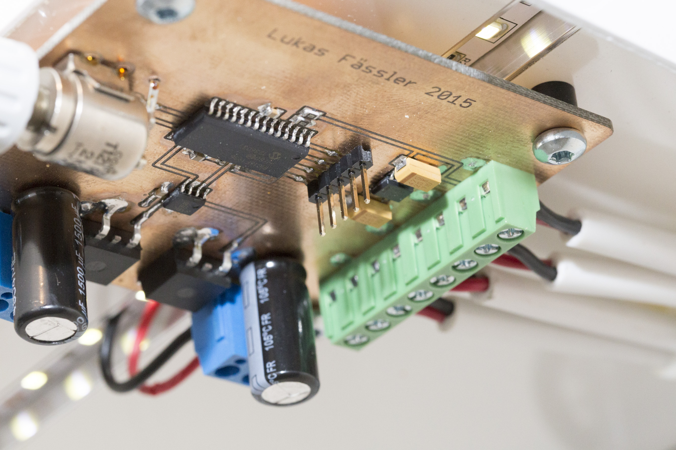
At the center of my design is a 8-bit PIC microcontroller, a PIC16F1936. There’s not much special about this particular model, it’s just a type I’ve used several times before and still had some on stock.
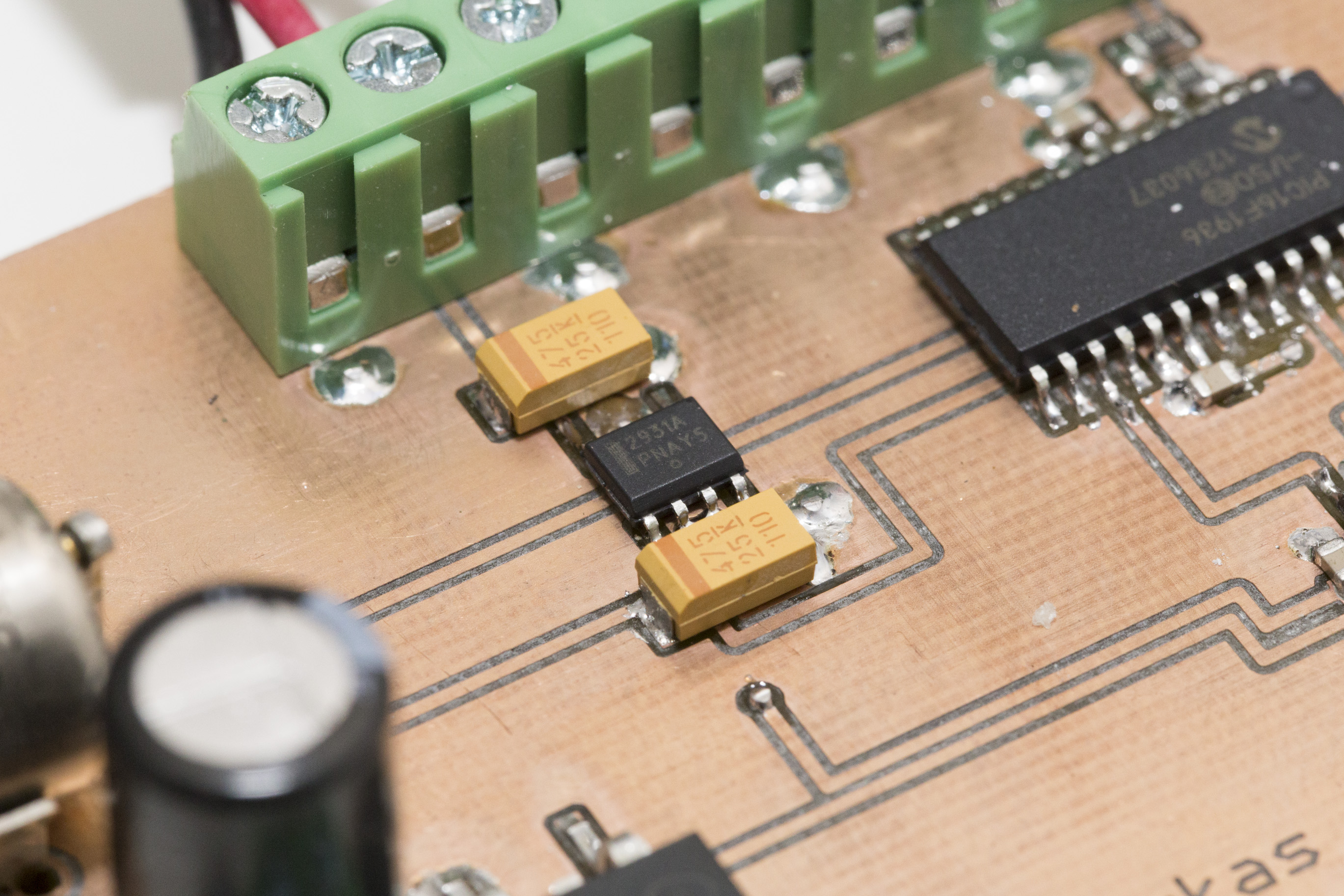
A LM2931 provides the PIC with 5 volts from the 12 volts input voltage. I use the LM2931 as my standard 5V regulator. It’s pin compatible with the legendary 7805 but survives input voltages in the range of -50 to +60 volts making it very robust against transients.
The PIC controls a LM5111 dual FET driver that provides a powerful 12V gate drive to a pair of Infineon IPB136N08N3 N-channel MOSFETs. This is the same transistor that I’ve recently used for my Arduino Solar Charger Shield. Its an inexpensive (< $1), large SMD type with an exellent Rds-on of 11.5 mOhms.
There are several variants of the LM5111. It comes in inverting and non-inverting configurations as well as combinations of inverting and non-inverting. At Farnell, the the inverting ones were by far the cheapest so that’s what I’m using here. It doesn’t really matter since you can change the polarity in software as needed.

Why am I using two FETs despite the fact that one could easily handle the entire current? First, I’m driving two LED strips with this dimmer and using two transistors simplifies the layout so I have two outputs exactly where I need them. Secondly, the LM5111 is a dual FET driver anyway so I get the second gate drive for free.

I’ve provided each output with a generous 1.5mF capacitor in order to shield the supply from the ripple that is inevitably produced by the PWM. I’ve also taken care to use a cap with low serial resistance (ESR) and a high current rating. The Panasonic FR series fulfills both of these requirements while being good value for money. I thought this should be enough to avoid excessive ripple and therefore also acoustic noise.

The input to the PIC comes from a quite nice 2 kOhms pot that I’ve recovered from some scrap. There is also a voltage divider to measure the 12V input voltage. The idea was to only enable the output once the input voltage has stabilized but I found this to be a quite unnecessary feature when programming the PIC.

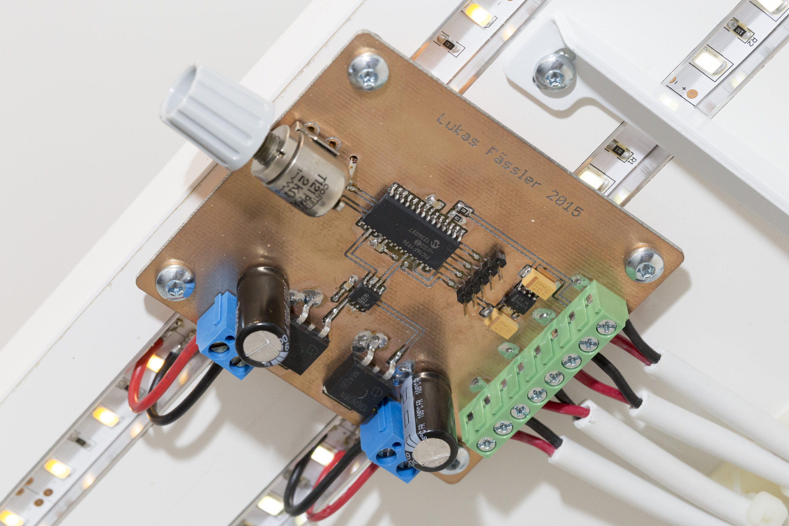
The Layout

I’ve built the two different versions of this dimmer. The schematic is exactly identical for both of them, they only differ in their physical layout and board dimensions. I’ve just tailor-made them to their specific application so the pots are located in a handy position and the outputs are exactly where I need them.

Software and Testing
My first version of the software measured the voltage from the pot using the on-chip ADC and outputed an identical 2kHz PWM signal on both outputs. 2kHz should be enough to avoid visible flicker and seemed a reasonable choice. Everything worked but the power supply made quite a bit of noise over most of the brightness range. Worse than any commercial design. Even worse, there was an awful lot of flicker. Ouch.

Looking at the power supply output / dimmer input voltage on a scope if became clear that the two 1.5mF caps still allow too much ripple at this frequency.
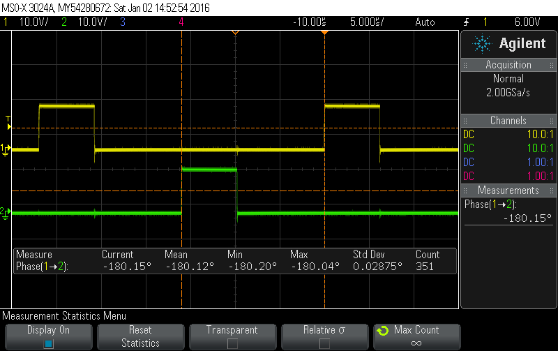
The first thing I tried was running the two outputs out-of-phase. Since I’m using two FETs I have two independent outputs. So I can run them 180 degrees out-of-phase. Now, at duty cycles below 50% it looks like I’m only driving a load half the size with a frequency and duty cycle twice as high. At precisely 50% duty the supply even sees a constant load at its output since exacly one LED strip is on at any point in time. At duty cycles above 50% the on-times overlap so the load only varies from 50% to 100% and with twice the frequency. As you can see from the scope screenshot below, this already helped a great deal but the problem was not yet resolved. So the natural thing to do was to increase the PWM frequency.

At 8kHz, things already looked (and sounded) much better. Ripple and acoustic noise were much reduced but the supply was still audible at least in a quiet environment.

So I moved the PWM frequency up as far as i could. Given the PIC’s 32MHz clock and a 10 bit resolution this was 31.25kHz. Now every last bit of audible noise was gone. Finally.

I then noticed that the phase shift was 176 degrees as opposed to the intended 180 degrees.

Not that this makes much of a difference in practice but I solved it anyway. I’ve implemented this phase shift by starting one PWM module at 128 and the other at 0 (we’re only talking about the 4 most-significant bits here, so the maximum is 255). The two instructions are on successive lines in my C code but 3 clock cycles are needed to process each of them so they are not enabled at the precisely same time. Starting the first PWM module at 131 has solved the problem as you can see below.
With these changes in place the flicker mentioned previously was also much reduced but had not yet disappeared. Looking at the voltages on a scope for a while the problem became clear. I was measuring the voltage from the pot at fixed intervals that had no connection with the switching frequency. So I was effectively measuring at random points in time.
I said that the input voltage now showed much less ripple but some ripple is inivitable. Some of that ripple is likely to somehow feed through to the voltage from the pot. That introduced noise in the value measured by the ADC which lead to variations in the duty cycle which was noticable as flicker.
I did two things to resolve this. First, I’m generating an interrupt signal (from the same timer as I use for the PWM) every 64 PWM cycles. In the corresponding interrup service routine (ISR) I read (and save) the ADC value and start a new conversion. This way I’m always measuring at the same point during the PWM cycle. So the effect of the ripple should be similar every time. I’m also averaging 32 measurements which further helps to smooth the value I’m using to calculate the duty cycle. So flicker is gone as well as you can see below.

Now for the transfer function. My first try was exponential. The problem with that was that it gave away too much of the pot range for very low brightness levels. I played around with this for quite some time and finally settled for a combination of linear (at the very low end of the range) and exponential (for everything above that). Also, two of my dimmers can be fully turned off by turning the dimmer all the way to the left. Their power supply is always on and the light is only controlled by the pot so I need to be able to really turn them off (not only down). The third one has a slightly different transfer function that only allows to turn it down to 2% or so. That one has its power supply controlled by a conventional light switch so I don’t want the pot to completely turn it off.

The result
After all, I’m very happy with the result. There is no noticable power dissipation on the board. There certainly is a bit of dissipation but the board doesn’t heat up noticably so I’d say its clearly below a watt.
The components have cost me around $10 per board. Some stuff like the connectors I have bought a flea markets, they can be surprisingly expensive through regular retail channels. The PCBs are home-made so they have cost me a considerable amount of time but not much in terms of cash.

They are, furthermore, controlled by a simple pot, produce no audible noise and can be finely dimmed just as planned. So I can proudly state that all the requirements have been met.
If you’re in need of a dimmer and have a soldering iron and a bit of spare time I can only encourage you to build your own. It’s not too hard, needs only few components and is very doable on a prototyping board if you don’t want to etch or mill your own board.
As always, attached is a zip file with all the eagle files, board layouts, schematic as well as the software.
I liked your discussion of noise and flicker. Have you thought about using an incremental encoder instead of a pot?
Hi Werner.
Thanks for your comment. Yes I’ve considered using a rotary encoder instead of a pot but thought a pot was more suitable for this project. I’ve done something similar with RGB LEDs where I do use a pair of encoders with push buttons. More about this in my next post.
Lukas
Why didn’t you also use a small (something <1µF) low esr (smd) ceramic capacitaor in parallel to reduce ripple? I don't think the huge 1.5mF electrolytics help that much.
Why didn’t you include a low esr ceramic capacitor (smd, X5R/X7R) into the design? At least the switching noise would be (significantly) reduced.
What was the audible noise like? Was it higher pitched than your base frequency?
Hi Martin. Good point. At least at low switching frequencies the problem was that the input voltage dropped as a result of the several amps of current suddenly demanded from the supply. I found the supply was quite quickly back in regulation, maybe after a few hundred microseconds. But when you’re switching at even a few kHz, a few hundred microseconds are a long time… And to help the supply during that time you mainly need capacitance.
You can see quite well on the scope screen shots what part of the ripple comes from the ESR and what is just a capacitor being charged and discharged. And the caps I’ve used are very low ESR for an electrolytic cap. Things change somewhat at higher switching frequencies where a lot of the noise is just spikes. There a ceramic cap would definitely help. I guess I’d add one if I build one of these again.
And about the sound it made. To me it sounded much like it was pitched at the switching frequency. And it definitely moved higher as the switching frequency was increased
Maverlously documented! Kudo for that.
I’m good with electronics but also did not learn how to surface mount solder… Where should i start?
Hi Buj. Thanks for your comment. I remember that my first project with SMD components was a struggle, too. But I quickly started to like them. Almost everything you see on this blog is soldered using a conventional soldering iron. Good, pointy tweezers are a must have. I also like to use thin solder, something like 0.5mm. It really gets easy with a bit of practice. There are a few good tutorials at eevblog.com. One of the best resources out there anyway. Dave shows how to solder ICs with a .05mm pitch using a conventional iron. And it just looks totally easy. I haven’t tried things that small but 0.65mm works quite well for me.
Thanks for the feedback I will try.
Since i wrote this i started to browse and saw solder paste in conjunction with a reflow (?) Oven . what’s your opinion on this?
I don’t think reflow is the way to if you’re just building one or two. It’s probably great if you’re building a series since you can just apply the solder paste in almost no time if you’re using a stencil. Just place the components and put them in the reflow oven. But for prototyping conventional soldering is quick and easy. Just google for “EEVblog soldering tutorial” and you should find a 3-part tutorial that I found useful at the time.
This is a matter close to my heart cheers. Thanks
Hi Philip
You may also like this new version: https://soldernerd.com/2017/04/30/programmable-led-dimmer/
Hello.
I really enjoyed my project, and wanted to know how to help me in something similar that I need.
An idea is much simpler than yours.
I need to control the brightness of a power led using pic12f675. The will lamp will be 12 V which needs 350 mA to be triggered. If you can help me, when I return this email I’ll give you the details.
Note: I am from Brazil, and I used the translator, I do not know English is adequate.
Hi Lukas,
I am making a similar PCB for a power output of 200W.
Could you send me your schematic of this project? I have also seen your renewed version, great stuff!
Kind regards,
Max Kielen
Mechatronics Student
Hi Max
Thanks and I’m glad you like the design. There is a link at the bottom of the post where you can download a zip file with all the schematics and everything. Chances also are that everything is on github.com/soldernerd
cheers
lukas
Hi Lukas,
me again haha…
Do you have any tips or suggestions for upgrading this to a 200W version? Switching to different components etc. If so, what components are needed to be upgraded?
Greets
Max
Hi Lukas,
me again haha…
Do you have any tips or suggestions for upgrading this to a 200W version? Switching to different components etc. If so, what components are needed to be upgraded?
Greets
Max