
There have been two previous posts on this project: one on the concept and the hardware and one on hardware testing. You probably want to check them out first if you’re not yet familiar with this project. Or even better: Click here for an overview over this project.
Now that we know that we have a functioning MPPT solar charger we are ready to talk about the software (or the sketch as the Arduino folks call it). It’s quite simple, really. So this will be a short post. And yes, you can download the sketch. There is a link at the end of this post. As always, I appreciate any feedback, comments and the like.
There is a number of basic tasks the arduino needs to perform in order for this shield to be useful. I’ll go through them one by one.
Controlling the DC-DC converter
At the heart of this project there is a synchronous step-down (or buck) DC-DC converter that is controlled by a PWM signal from the arduino. So one of the tasks is to set the frequency and duty cycle of that PWM signal.
We let the PWM signal run at the maximum frequency the arduino allows with an 8 bit resulution. Thats simply 16MHz (the Arduino’s frequency) divided by 256 (the 8 bit resolution), or 62.5 kHz. So the prescaler will be 1.
As you can see from the shields’s schematic, we need to output the PWM signal from Pin 6 (by the Arduino’s pin numbering, not Atmel’s). In order to do this kind of low-level stuff you’ll have to read the Atmega328’s data sheet. There is usually no Arduino-ish shortcut if you really need to controll what’s going on.
Luckily it’s just a few lines of code to set things up. All in the function buck_setup(). There are three more little functions to control the DC-DC controller once it’s set up:
buck_enable() and buck_disable() are very simple and just turn it on and off, respectively. buck_duty(uint8_t duty) is only slightly more involved. It changes the duty cycle to the value you pass to it. Besides that it ensures that the duty cycle stays within certain limits.

You don’t want it to go to 100% since in order to keep the bootstrap capacitor C6 charged you need a little bit of off-time. In order to drive the upper FET you need a voltage higher than the panel’s voltage and that’s exactly what C6 is for. So we enforce an upper limit on the duty cycle.
Likewise, you don’t want your duty cycle to go below 50% because in that case you would be pumping energy from the battery to the pannel. A synchronous step-down converter is basically the same thing as a synchronous step-up (aka boost) converter with input and output confused. So we also want to enforce a lower limit on the duty cycle.
The upper and lower limits are set through the #defines DUTY_CYCLE_MINIMUM and DUTY_CYCLE_MAXIMUM.
Measuring voltage and current
The shield has all the hardware necessary to measure both voltage and current both at the input as well as on the output. We’ll just need to write some simple software to make good use of that hardware.
Unlike with the PWM singal where we had to do some low-level bit fiddling ourselfs we can just rely on convenient Arduino library functions to do the job. Basically, analogRead() is all we need here.

I’ve written a function called read_values() that uses analogRead() to read all 4 values (input voltage, output voltage, input current and output current) 16 times each, averages the results and converts the ADC reading to proper voltages and currents.
The necessary multipliers are defined as floats in VIN_MULTIPLIER, VOUT_MULTIPLIER, IIN_MULTIPLIER and IOUT_MULTIPLIER. I’m doing all the voltage and current measurements in floating math. Yes, this is not at all efficient but we don’t need the Arduino’s computational power for anything else most of the time so this is fine here. Just keep in mind that you can save a lot of resources here if you ever need to do so.
Displaying voltage and current on the LCD
Our hardware also involves a 2 lines x 16 characters LCD so we can show the world what we are measuring. Again, we can rely on standard Arduino functionality to do the job. There is an LCD library that does everything we need.
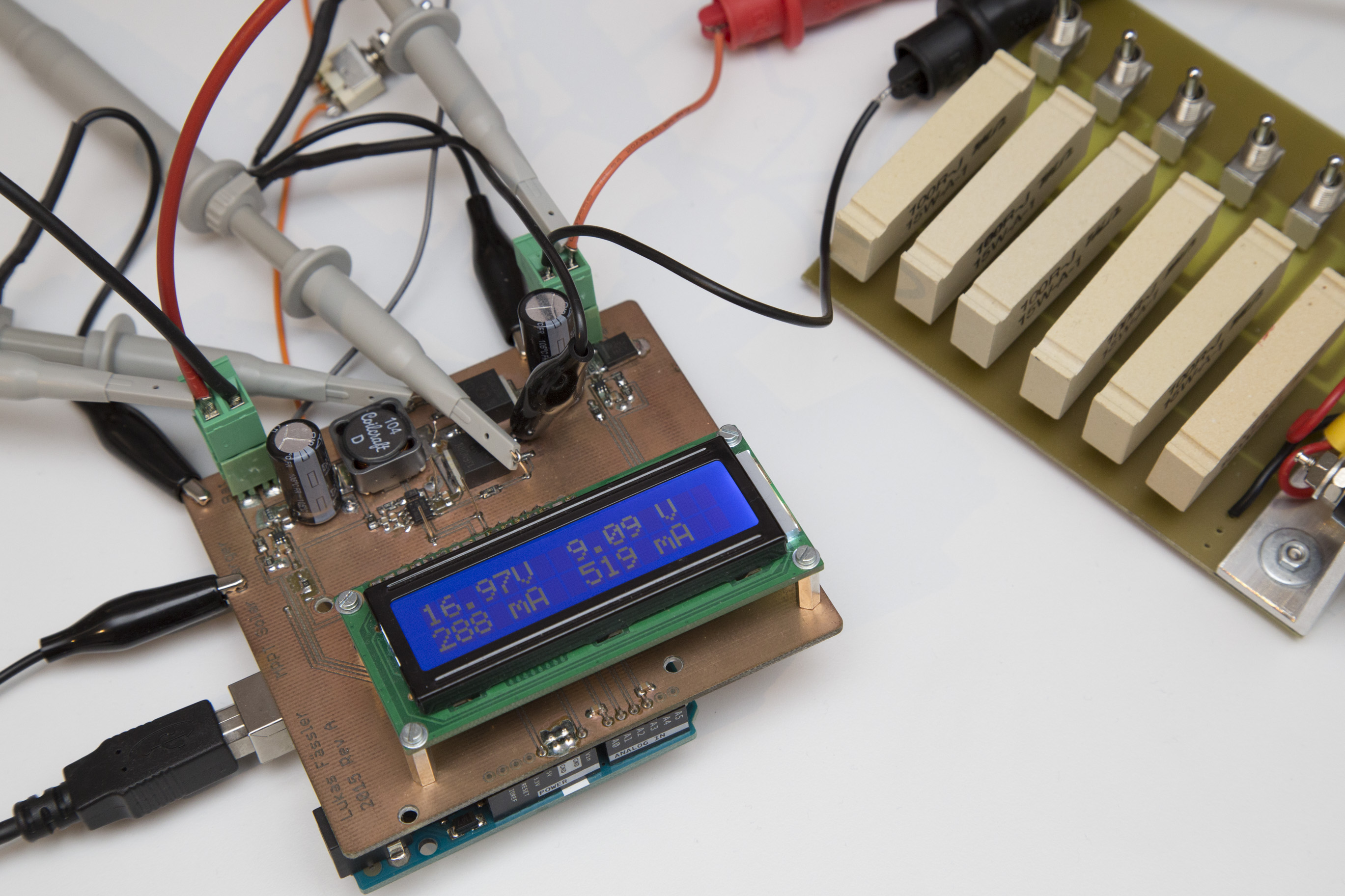
So my function write_display() can focus entirely on formatting. The upper line shows the voltages in Volts, the lower line shows the currents in Milliamps. The input is on the left hand side of the display, the output on the right.
Deciding what to do
In the first section we’ve discussed the functions necessary to controll the DC-DC converter. But in order to use those functions, the Arduino needs to first decide what to do.

This is where the function buck_update() comes into play. You could consider this the heart of this sketch. This is where all the relevant decisions are made. When to turn the converter on, when to turn it off, when to increase the duty cycle, when to decrease it… You get the idea.
The behaviour of buck_update() is controlled by 8 #defines. I list them here together with the values I have used:
#define ENABLE_VOLTAGE 18.0
#define DISABLE_VOLTAGE 15.0
#define INPUT_TARGET_VOLTAGE 17.0
#define OUTPUT_TARGET_VOLTAGE_LOW 13.8
#define OUTPUT_TARGET_VOLTAGE_HIGH 13.9
#define INPUT_CURRENT_LIMIT 2000.0
#define OUTPUT_CURRENT_LIMIT 3000.0
#define INPUT_CURRENT_MINIMUM 0.0
I think they are quite self-explanatory, especially if you look at how they are used inside buck_update. It’s quite simple: If the panel’s voltage rises above 18V, turn the converter on. Once the converter is on, try to archieve a panel voltage of 17V without exceeding 13.9V at the output. If the panel’s voltage drops below 15V turn the converter off again.

Besides that the function is also looking at the input and output current and makes sure certain limits are not exceeded. But with a 30W panel it should never be possible to reach those limits anyway.
Putting it all together
Now all we need to do in the loop() function is calling read_values(), buck_update() and write_display(). Since writing to the LCD is quite slow we are only doing it every 32nd time we read the values and update the PWM signal.
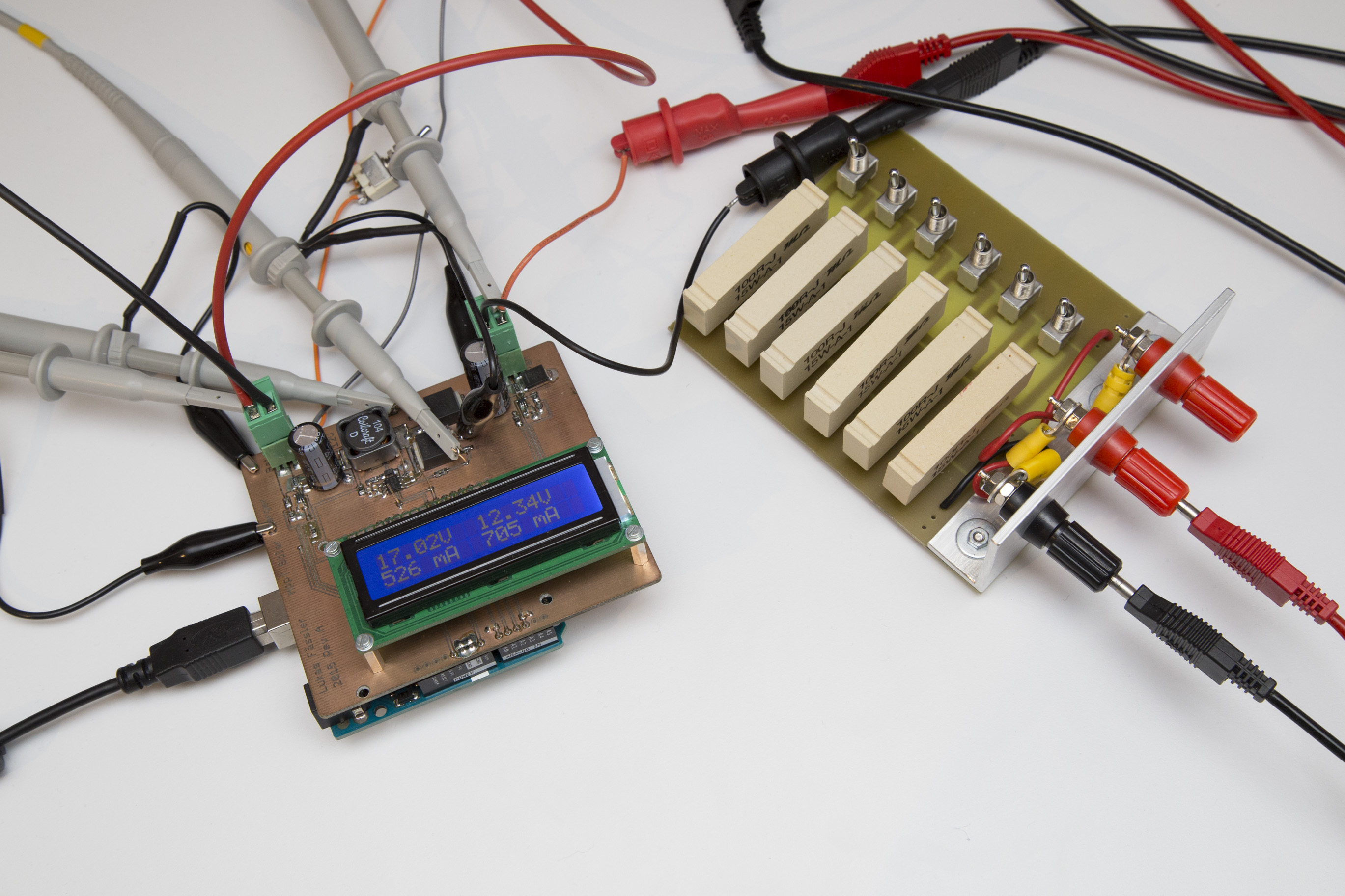
With this sketch I’ve hooked the MPPT Solar Charger up to my lab power supply. (a Keysight E3645A, my newest toy *g*) and my extremely simple but occasionally useful resistor-based dummy load.
The enable and disable voltages are simple and work as expected. Maximum output volage is also not tricky. If the voltage at the output goes too high, the duty cycle is decreased and everything is fine again.
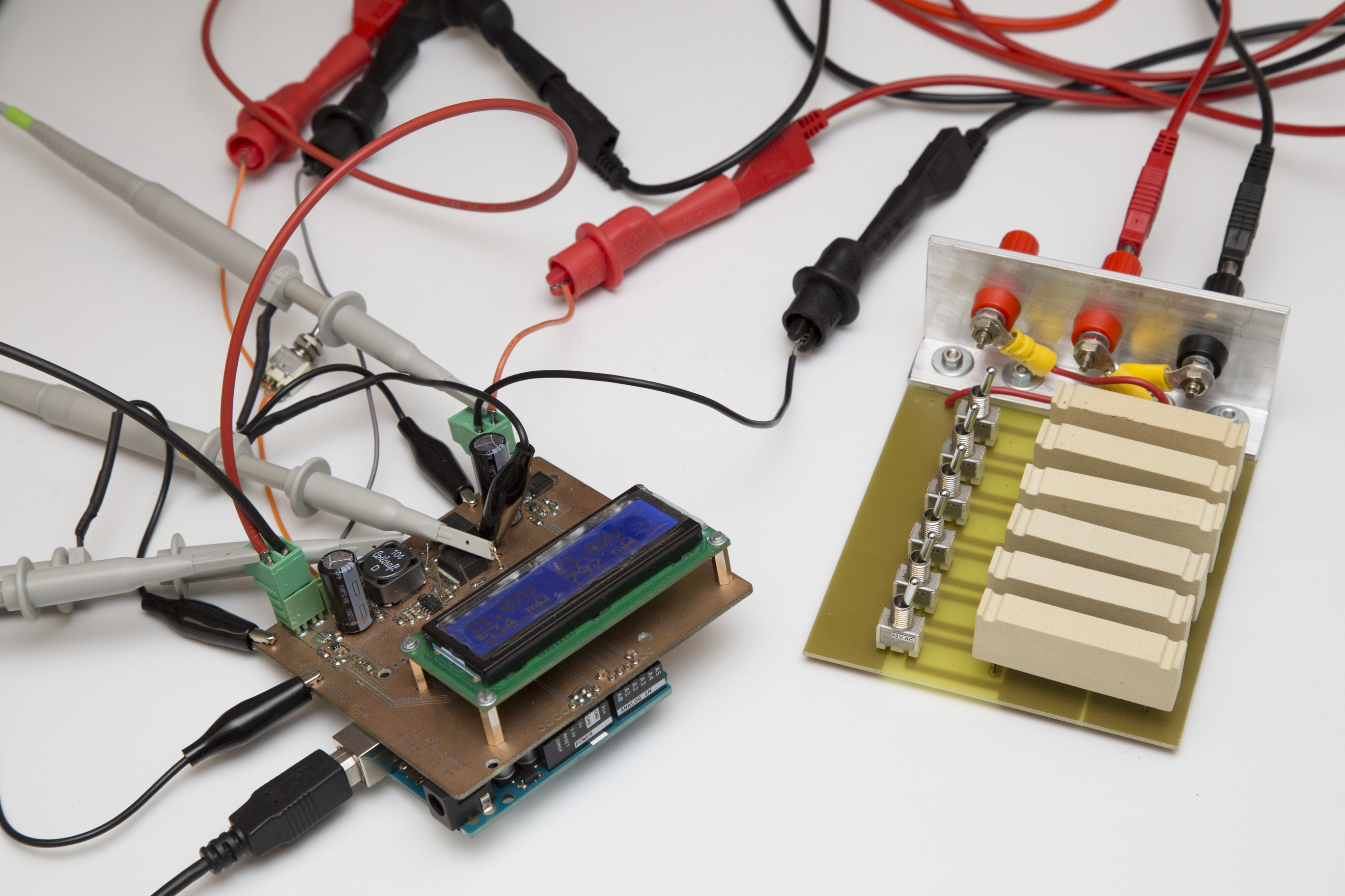
More interesting was to see how the shield would regulate when faced with a limited current budget at the input. For that the supply was set to a voltage of 21V (about a 12V solar panel’s open-circuit voltage) with a current limit of 100mA to 500mA. That’s quite a nasty supply, quite a bit trickier to handle than a real solar panel. Try to pull just a bit too much current and the voltage will drop to zero…
Also, the resistors at the output are not a realistic load for the converter. A car battery will pull no current at 12 volts or so (unless overly discharged) but will quickly start to sink large currents when the voltage goes just a bit higher and the battery is charging.
But I think the setup is good enough to test the sketch. And it handles the challenge quite well. With all resistors on (i.e a 100/6 ohms load) and a 300mA current limit, the input voltage sits at 17V (our target input voltage) while 9.25V appear at the output. At 400mA, the output voltage rises to 10.7V with the input still at 17V. At 600mA the input is still at 17V but with the output now at 13.15V. If I take the current limit even higher, the output voltage rises to 13.82V but not any higher, just as we want. The input voltage rises to 21V (since this is a lab supply and not a panel) with a corresponding drop in current to 530mA.
I’m honestly quite happy with the project as it is now. The idea definitely works and I’m motivated to design a new, deployable version with some fancy features that will use much less power at the same time. I’ve already done quite some work on that new version but it will take another few weeks until I get to describe that project here.
Until then I will show you some other, smaller projects that I’ve already finished but didn’t have time to document yet. So you will first see a number of smaller, simpler projects over the next few weeks.
Before I forget: There’s the Arduino sketch for download. And click here for an overview over this project.
Update: Now there’s an entirely new design.
Well illustrated post.
I’m looking for info on solar charging LiPo batteries – there seems to be very little information or products on the market for these. Everything is geared towards lead acid batteries!
Specifically, I have a 48V battery pack comprising ten 6S lipos, arranged as 2 serial 5 parallel that I made for my ebike.
What I’d like is to be able to keep it float-charged and balanced via solar, and can’t find anything on the net that can do it, so I’d like to try a custom build.
MPPT would be ideal, and I have a couple of spare Arduinos I can use.
Thing is, I have no idea what components to use to be able to handle up to 500W of solar panels @ 18 or 36V to track and convert to 48V output (2 x 24V) with 12 balancing wires, each able to maintain a programmable float range between 4.0 to 4.2V per cell.
It may be easier just to use an MPPT unit as a power supply to drive two standard lipo chargers with separate grounds, though every MPPT devices I have seen are controllers and not just basic power supplies.
I think lipo charging will be a big market soon due to the rise of electric vehicles, ebikes and home battery banks.
Would be great to be able to parameterize MPPT for any specification, and then provide all the component specs…
Would be interested in your thoughts.
Hi Andy
Thanks for your lengthy comment. I do have experience with LiPo batteries from a RC helicopter that I used to fly. But those were much smaller, like 11.1V 2.2Ah. I’m not too worried about building a MPPT that can handle 500W @ 48V. Current-wise that’s the same as 125W @ 12V and that’s very doable with a beefier inductor and a bit of heat sinking on the mosfets. But I have no experience with balancing. I’d go with a off-the-shelf LiPo charger/balancer if possible. Efficiency-wise that not a great solution but I’d start with that. Do you know more about how those LiPo balancers work?
lucas,
great concept, I started to modify it to use up to 150V (for thin film panels from solar frontier) and 48V batteries. I added a synchronous downconverter from the battery to local supply, controlled if there is enough sunshine Vin>vbat. I replaced the surrent sensors by allegro acm712, and made room for a teensy 3.2 running at 72Mhz. current depending on inductors up to 30A. plus a solar panel reverse current switch in the neg rail, driven by the same Vin>Vbat
gruetzi,
Koen
Hi Koen
Thank you for your comment. Sounds really interesting. Would be nice if you had some photos and/or schematics to share…
Lukas
Sir i have a 600watts solar array charging 6 12v batteries. what do i need to do to make this circuit suitable for this spec.?
Hi Slide
It doesn’t take that much. Basically, there are only three components determining the power handling capability: The coil, the two power mosfets and the input and output capacitors.
The capacitors can just be scaled up linearly. The inductance of the coil needs to be smaller (!) in order to handle more current but its current handling capabilities must of course be higher. Twice the power means half the inductance, half the resistance and twice the saturation current. For the mosfets you definitely want some larger package that works with a heat sink, typically a TO-220.
Let me know how it goes.
Been following this with interest, aiming to design and make a smaller shield style PCB. Have you shared the schematic for this ?
I am aiming to build it as an ESP8266 shield to include data logging/upload capabilities as well.
Never mind found the rev 1 schematic in Eagle. What is your licence on this ?
License? Well I haven’t explicitly published under any specific license but it’s there for people to use. So feel free use and modify it as you see fit and let me know how it goes.
HI Lukas,
I will wait your news about this Project. I think is better to “finish” your MPPT controller as it began, I mean, with 12V and 30W, and after, explain about several options like: 12V/200W, 24V/300W, 24V/600W.
I think is better to check it with less power not to burn anything important.
I hope I can read news soon.
Regards,
Hi juan
Thanks for your comments. I’m currently really busy with my Ultrasonic Anemometer project but that doesn’t mean that I’ve lost interest in this solar charger project. I hope to find the time to continue it later this year…
regards
lukas
The Sky-sailor solar plane guys also designed a mppt. In there Thesis the following is descriped;
“A “Hill Climbing” method was used for the algorithm. At a frequency of
100 Hz, the current and voltage are measured on the output of each DC/DC
converter. The calculated power once compared with the previous value
allows changing the gain into the correct direction. This technique was tested
and found to be efficient enough to track the maximum power point even
when the irradiance conditions change rapidly.”
Page 97;
http://www.sky-sailor.ethz.ch/docs/Thesis_Noth_2008.pdf
So instead for targeting for a fixed input voltage. You can also target for the highest watts, and adjust the input voltage accordingly.
Hi Sjoerd.
Thank you for sharing this link. I’ve read about what you describe as hill-climbing algorithm as “perturbation and observe”. You measure the input power and keep going in one direction (increasing or decreasing duty cycle) until power declines. You then go in the oposite direction until power declines… I agree that this is probably the way to go. Some combine it with an ocasional scan over a large range to avoid getting trapped in a local maximum but I think usually that is not even necessary.
regards
lukas
local max is only a problem with partial shading on a large series connected PV array. not the case here ..
Thanks for that insight, Koen. I was aware that non-monotonic behaviour is usually caused by partial shading. However, I didn’t know that this is only a concern with larger arrays. Good to know.
it actually depends on the reverse diode and how many have been applied. some panels only have a reverse blocking diode on their output. this one activates when more current is generated by the other panels (shading) and the voltage of the weaker panel drops to zero. sometimes panels have local internal strings with reverse blocking diode per string, this is being advertized by some diode manufacturers, to reduce the effect of local shading per panel.
The definitions for DUTY_CYCLE_MINIMUM and DUTY_CYCLE_MAXIMUM can no longer be found in software revision B.
I am wondering what the step size is, in which your code modifies the PWM duty cycle.
I get the foggy idea that DUTY_CYCLE_MAXIMUM is often advertised as MPPT tracking efficiency. And that 100% – MPPT tracking efficiency is the step size. That is 99.9% -> 0.1% step size and 98% results in PWM duty cycle step changes of 2%.
Hi Ceriel
I guess I’ve just renamed them or something, I’m quite sure they still exist. They now probably differ between synchronous and asynchronous mode. The reason for these limits is to keep the duty cycle in a safe range. This is particularly important in synchronous mode where you can actively pump energy from the battery to the panel if your duty cycle is too low. This has happened to me before and kills the current monitoring IC at the panel when the voltage exceeds 26 volts.
Duty cycle is only very remotely related to efficiency. And yes, some vendors advertise 100% duty cycle but this doesn t make any sense. A buck can not possibly run at 100% because it needs the off-time to re-charge the bootstrap capacitor. Anything above, say, 98% is nonsense. I usually limit it to something like 95% even.
hope that helps
lukas
The step size is 1 at a resolution of 256. The re