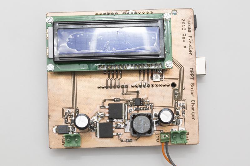
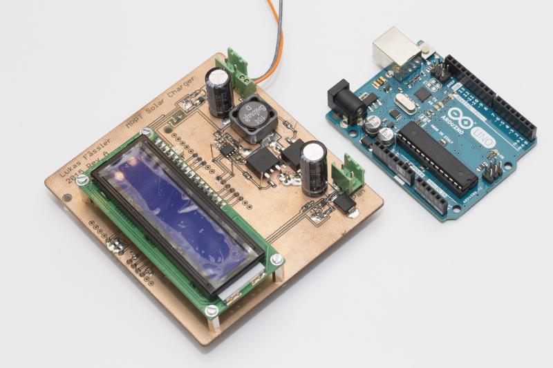
A friend has approached me regarding his solar project. He wants to install a solar panel together with a battery and an inverter in order to have power at his allotment garden. He had looked at a hobbyist project where an arduino was used to build a MPPT (maximum point of power tracking) charge controller. I took a look at the design, liked a lot of what I saw and decided to build something similar.
The basic idea behind an MPPT solar charger is simple. A solar panel has a certain voltage (in the region of 17 to 18 volts for a 12 volts pannel, somwhat dependent on temperature) at which it provides most power. So as long as the battery needs charging, you want to pull just as much current to reach this voltage. But once the battery is full you need to avoid overcharging the battery. So you want to maintain a maximum voltage for your battery (somewhere around 13.8 volts for a 12 volt lead acid battery) and no longer care about the pannel’s voltage.
So the charger needs to convert an input voltage of 17-18V to an output voltage of 12-14V as efficiently as possible. Obviously, a step-down (aka buck) switching converter is ideally suited for the job. However, a typical DC-DC converter is designed to maintain a stable voltage at it’s output, independent of it’s input voltage. As described above, our requirements here are different.
Switching converters are controlled by the duty cycle of a (typically) fixed-frequency PWM signal. So a microcontroller could be used to do the job. In most applications, this wouldn’t work that well because a microcontroller would be too slow to react to sudden changes in load or input voltage. But this is not much of a concern in our solar application: Sun intensity changes within seconds at best and the battery will absorb any sudden changes in load. So if we adjust our duty cycle a few times per second we’ll be more than fine. And that’s easy to do with a microcontroller.
The next step was to figure out at which frequency to run our converter. An arduino runns at 16MHz. At a 8-bit resolution, this gives us a maximum PWM frequency of 62.5kHz. That’s a pretty slow speed for a switching DC-DC converter nowadays. Most modern designs run in the hundreds of kHz to a few MHz. The main reason of using higher and higher switching frequencies is size. The higher the frequency, the smaller the inductor can be. For us, using a somewhat bigger inductor is totally acceptable. And in terms of efficiency, a lower frequency is even preferable since it reduces switching losses.
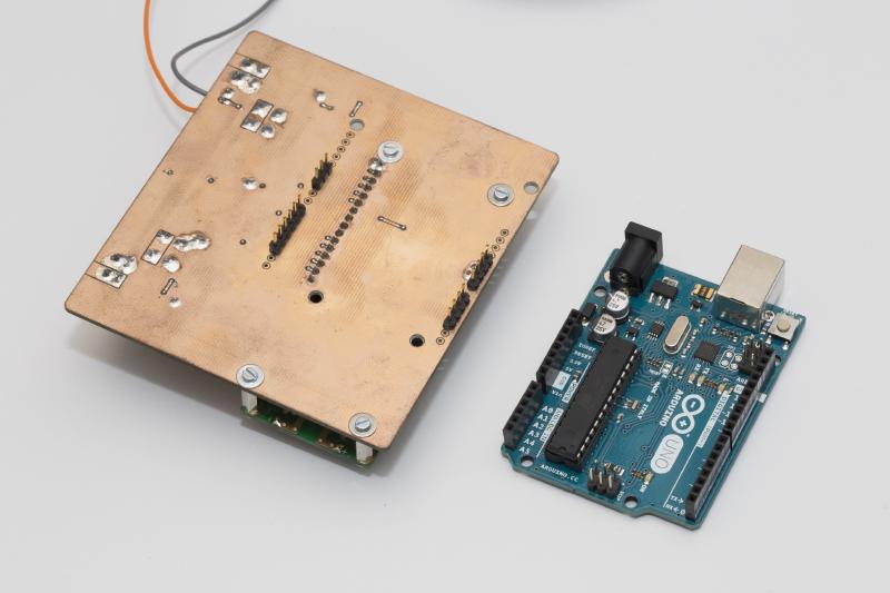
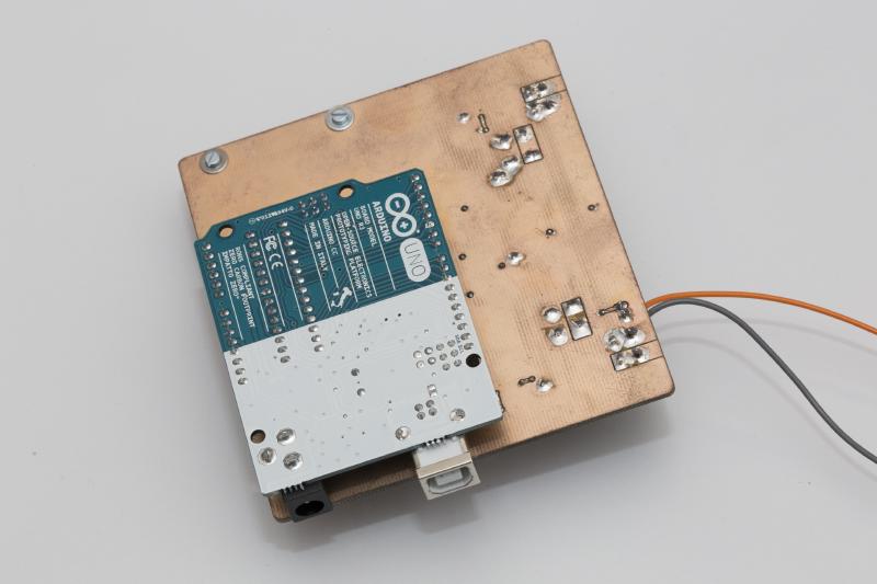
The project here is intended mainly as a proof on concept. I expect it to be fully functional but it will consume quite a bit of power while sitting idle. The display (including backlight) is always on, the same goes for all the other components. But the main drain on the battery will be the Arduino itself which consumes around 50mA when running at 16MHz. That might not sound like much but it will add up during the many hours the solar panel doesn’t produce any power. The system will be installed in Zürich, Switzerland so you can’t count on having 8 hours of sunshine every day. In winter, there might be snow on the panel, preventing it from producing anything for weeks in an extreme case. So a productive system should draw hardly any current (say <1mA) when not doing anything useful.
At least for now, the we’ll be using a 30W 12V monocrystaline panel and a 45Ah car battery. So I’ve scaled this converter to comfortably handle 30W input power which translates to about 1.8 amps at the input and 2.5 amps at the output.
As deba168’s design, I’m using a synchronous buck topology. If you’re new to switchers, you might want to check out this wiki page. If you’re serious about designing your own you might want to read Sanjaya Maniktala’s ‘Switching Power Supplies A - Z’, it’s a great book. I’ve also read his other two books on the topic but this is the one I love the most, especially to start with. I’m also using the same half bridge driver (IR2104) even though I find the 540ns off time somewhat excessive. But I like the enable/pwm input signals as opposed to having to drive each fet individually and I found this feature to be somewhat rare.
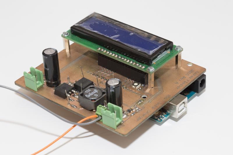
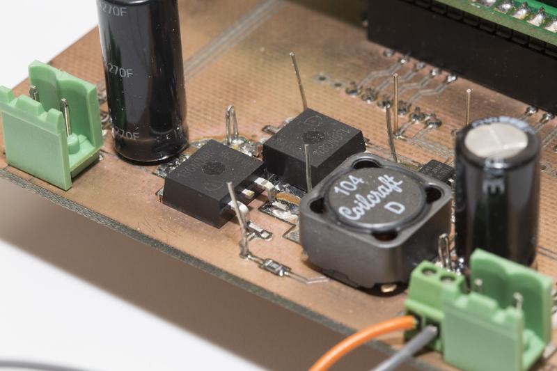
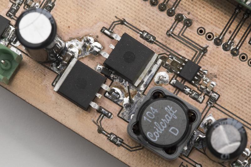
Apart from that I’ve really done my own design, mainly using parts I’ve still had from previous projects. As most stuff I build, it’s entirely SMD, except for the input and output capacitors. Not only are SMS designs smaller in size. The parts are much easier to source (and often cheaper) than conventional through-hole components nowadays. And contrary to popular belief, with a bit of practice I find them easier and faster to solder.
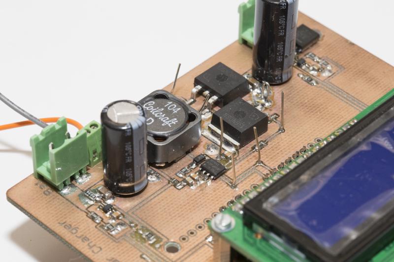
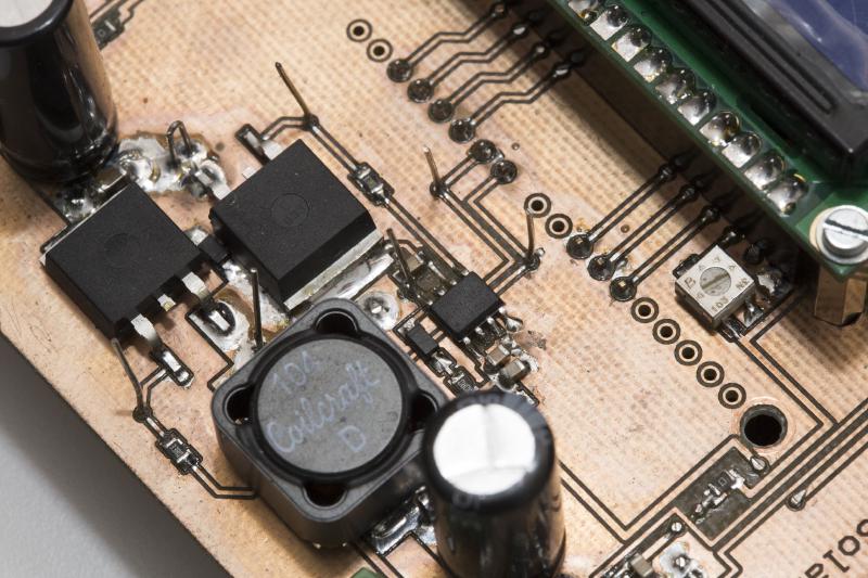
The FETs are IPB136N08N3, a quite large surface-mount type that I use quite frequently. They have a 11mOhms Rds-on resistance which will be great for efficiency. They are also easy to drive in terms of gate capacitance. Probably a bit oversized for the 2.5 amps we’re trying to switch here but I still have some here and they’re not expensive, around 70 cents each. The inductor is a 100uH Coilcraft MSS1583 with a resistance of 0.103 ohms and a 2.8A current rating. 100uH is a bit much at full load, 68uH would easily do. But the system will spend most time at moderate loads (remember, this is not California). I’ve ordered a 68uH as well and intend to use it for a later design or maybe to see what difference it makes. Input and output caps are quite a bit oversized as well, 680uF 35V at the input and 820uH 25V at the output. They are from the Panasonic FR series which I like using for my switchers since they work well at frequencies up to a few hundred kHz while being afordable and having very high ripple current ratings.
I’m doing voltage and current sensing at both input and output. I’ve decided to use conventional high-side, shunt resistor based current sensing. The Texas INA213 are fairly precise, work up to 26 volts and have a fixed gain of 50. Also here, I still had some left over from my dummy load project. Most components are much cheaper if you buy 10 in stead of just one or two so I tend to buy 10 ;-)
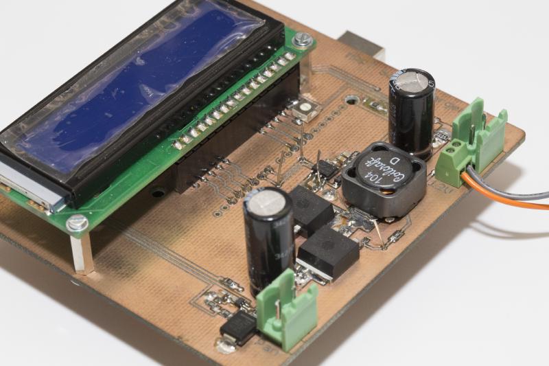
I’ve also added a standard 2x16 characters LCD display so I can see what’s going on. And you may have noticed that I’ve put a zero ohms resistor at several places. This will enable me to easily measure current consumption of the respective sub-circuit. As mentioned before, current consumption will play a major role in the final design so I’m interested to see how much juice is used by certain components under real-life conditions.
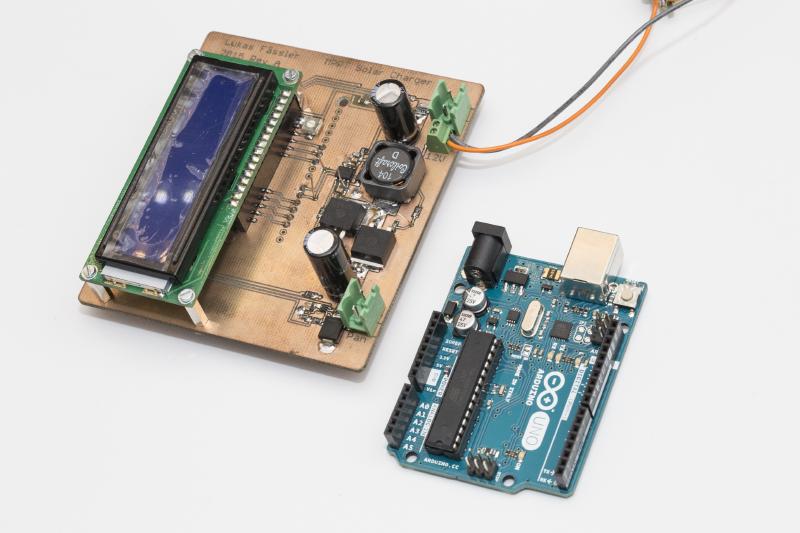
Besided the connectors for the panel and the battery, I have added a separate connector for the power supply. This is handy for early testing and programming. Just connecting this supply will power up the entire system. The arduino, the display, the converter and all. But there is not yet any load at the converter’s output and no supply at it’s input. So I can start programming the Arduino, start measuring and displaying voltages and currents and even turn on the converter to see if everything behaves as expected. And since there is nothing at the converter’s input and output, not much can go wrong. I don’t risk blowing up the FETs due to a bug in the program or a problem with the board. Only once I’m confident that everything works as expected I will connect a panel and a battery. At that point, the 12V input can just be connected to the battery as well.
I’ve written a simple sketch for the Arduino that measures voltage and current at the input and output and displays the result on the LCD. Once the input voltage exceeds a certain threshold, it will enable the half bridge driver and start switching. It starts at a duty cycle that will produce an output voltage equal to the current battery voltage. That means that no current will flow to the battery yet so the converter can start up with no load. Once the switcher is turned on, the Arduino will adjust the duty cycle about 4 times a second. If the input voltage is above its optimum and the battery has not yet reached its maximum voltage, the duty cycle will be increased by 1/255. If either the battery voltage is too high or the input voltage is below its optimum, the duty cycle is decreased by 1/255. There are also some checks for overcurrent at the input and output.
The switcher is turned off when the input voltage or the output current falls below a pre-defined threshold. This is a synchronous converter so current can flow back from the battery to the panel. We can’t just wait for the input voltage to fall. As long as the switcher is on, the input will never fall because energy is pumped from the battery to the panel. A synchronous buck converter is just the same as a synchronous boost converter with its inputs and outputs inverted. So we need to make sure current is actually flowing to the battery. Luckily, a car battery will always draw a clearly non-zero current at 13.8 volts, even when fully charged. So when current stops flowing to the battery, we know the panel is no longer able to provide any power and we can or rather must turn the converter off.
This post ist getting rather long so I’ll stop here and will write another post later about how the circuit has been performing and what I have learned so far. I guess this project will turn into a little series, maybe with further (and hopefully improved) versions being developped. Looking forward to that.
Before I forget: Here’s the eagle files as well as schematic and layout PDFs as a zip file: SolarCharger_Rev1 (file no longer available).
Update: Click here to see how the shield performs or here for an overview over this project.
Update 2: Now there is an entirely new design.