

This is a constant current dummy load. It’s controlled by a PIC16F1936 microcontroller. As you can see, it’s equipped with a 4×16 character LCD display and, less obvious, a rotary encoder with push button. It accurately sets the desired current via a 16bit DAC and reads both current and input voltage with a single-channel 16bit ADC each. Temperature is measured by the microcontroller’s internal 10bit ADC.

It needs a 6…16 volts supply for it’s own use. That’s what the upper pair of banana plugs is for. It can then burn up to 4.5 amps in the range of 0…22 volts. You can set any current from up to 4.5 amps in 1mA steps via the rotary encoder. By pressing the encoder you can set the ‘sensitivity’ of the encoder. There are 3 ranges: 1mA, 10mA and 100mA per (encoder) step. This way, you can quickly and precisely set any current you want.
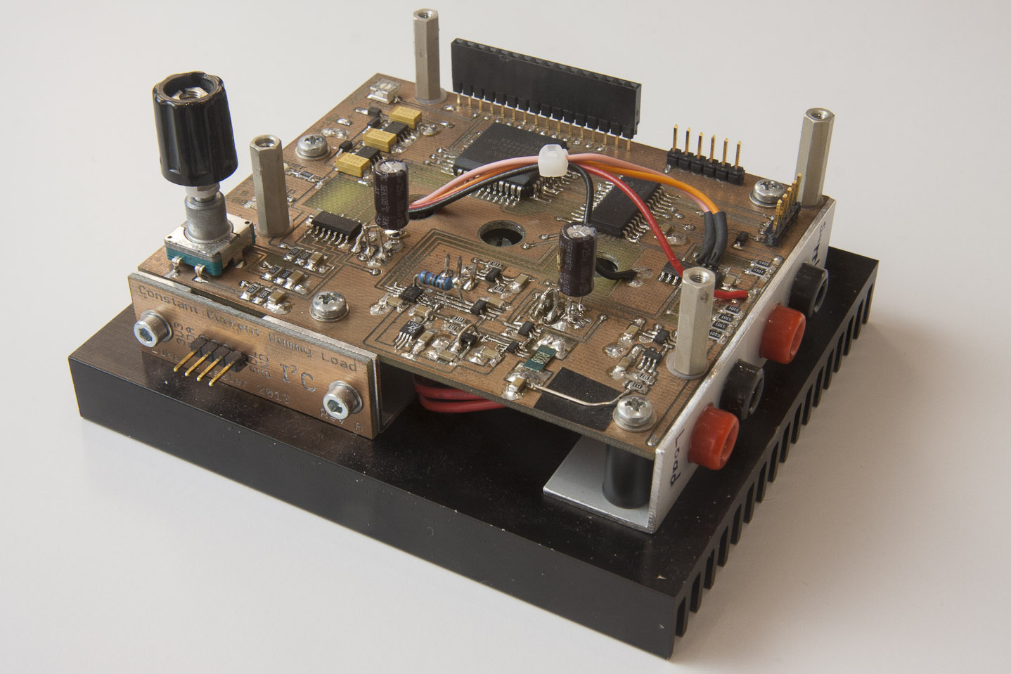
There is a LM35 temperature sensor mounted directly to the heat sink. The temperature is shown on the display as well as used for protective purposes. The software automatically limits the current if the heat sink gets too hot. Using the temperature, current and voltage, it also calculates the die temperature of the two MOSFETs and makes sure their temperature rating is not exceeded. They have a temperature rating of 125 degrees centigrade and a die-to-heatsink thermal coefficient of around 4 degrees/Watt. So with higher voltages and currents it’s entirely possible to blow the MOSFETs even with moderate heat sink temperatures.

You might wonder what the Xilinx XC9572XL CPLD is doing on there. Well, this was my very first project involving an LCD display, my first project involving a rotary encoder, my first project involving external ADCs and DACs… My first project at a lot of things. So I appreciated having the flexibility to change some of the signal routing in VHDL. All the signals traveling from the rotary encoder to the microcontroller and from the microcontroller to the display travel via the CPLD so I can re-route those signals any way I want. Now the CPLD mainly takes care of the encoder
The 100mil header at the front is a I2C interface that let the dummy load communicate with the outside world. It was added later so i had to run some wires to get access to the I2C bus.
By the way, this is how I got the idea of building a dummy load: http://www.eevblog.com/2010/08/01/eevblog-102-diy-constant-current-dummy-load-for-power-supply-and-battery-testing/
Great project. I liked very much your solar panel converter. Congratulations.
Thank you, Santi.
Hi, the pcb is great! What method do you use to build it?
Hi Mauricio
Thanks. The PCB was milled on an LPKF S62 mill/drill machine.
Lukas
Are the schematics still available?