
It’s been a while since I posted the last update on the anemometer project. The reason for this is that I’m struggling with the aerodynamical design.
By the way: Click here for an overview over the ultrasonic anemometer project: https://soldernerd.com/arduino-ultrasonic-anemometer/
For my very first tests I had misappropriated my wife’s hair dryer to generate some wind. Of course the results wereneither reliable nor repeatable so I built myself this ghetto wind tunnel:

It’s basically a 120x120mm square tube, made of cardboard and about 1.4m in lenght.

It’s powered by a powerful 120mm size brushless fan drawing some 2.25 amps at 12 volts. I don’t know about the air throughput but it generates a loooot of wind for a fan this size.
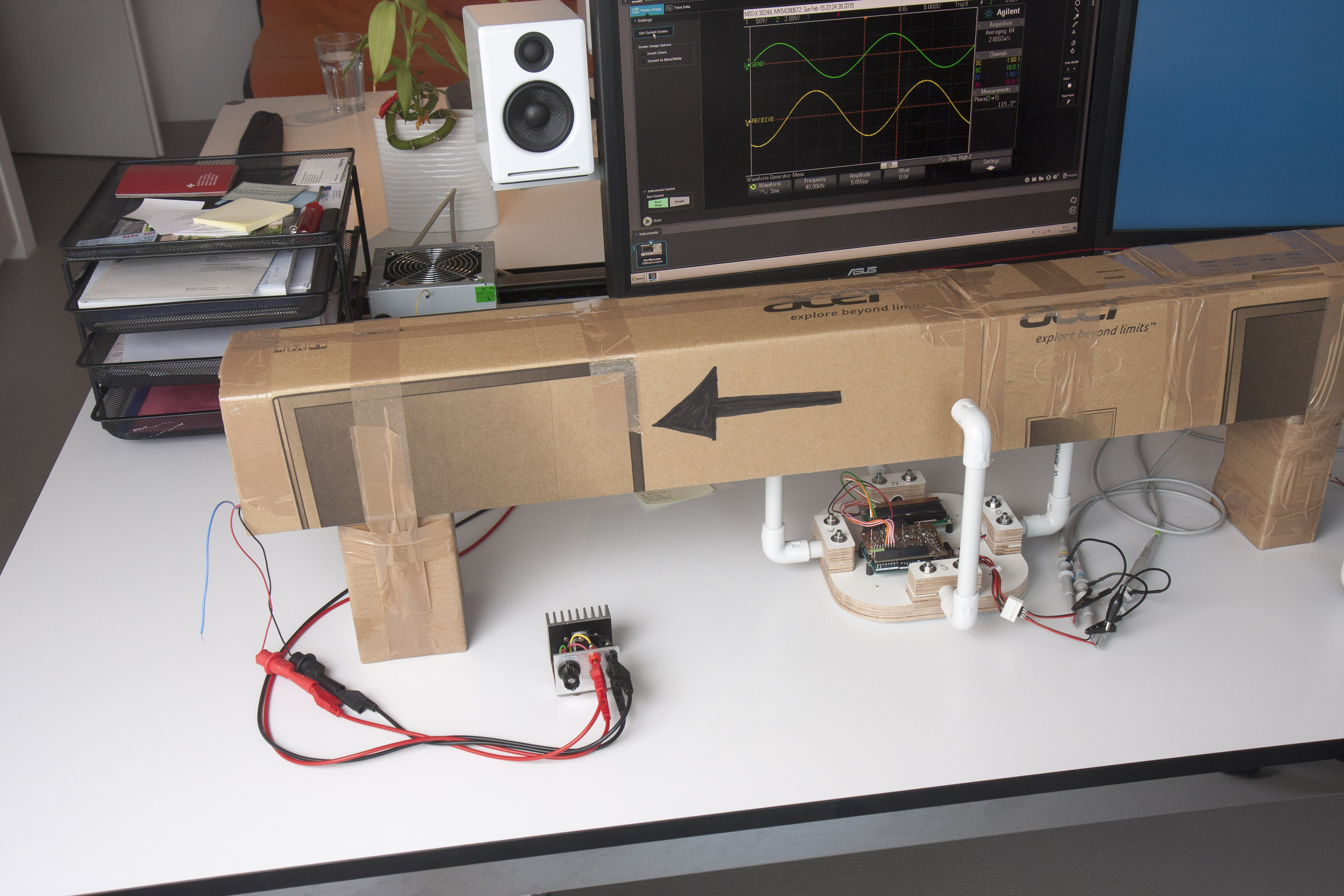
The legs put it at the right height for the anemometer prototype. There are two holes at the bottom through which the anemometer’s arms can be inserted. The transducers are then nicely centered inside the cardboard tube.

I can regulate the fan speed using a simple LM317-based regulator. It might look familiar to some of you, it has it’s own post here: http://soldernerd.com/2014/11/10/variable-voltage-power-supply-using-a-lm317/
Unfortunately, the LM317 is only good up to 1.5A so I have to connect the fan directly to my 12V supply in order to run the fan at maximum speed.
As you know, the main indicator of wind speed is the phase shift between the transmitted and received signal. The distance is 0.21m and speed of sound is approximately 340m/s so with no wind, the signal travels about 618us. Signal frequency is 40kHz so one full wave corresponds to 25us. So a full wave (or a phase shift of 360 degrees) translates to a wind speed of around 14m/s or 50km/h.
Note that we usually calculate the difference in phase shift measured forth and back.In that case, the signal already repeats at half that wind speed or 7m/s.
Now my impression was that I don’t get nearly as much phase shift as I should. What makes this difficult is that I don’t know the true wind speed so maybe the wind is just not as strong as I think it is.
I went back and checked my code but didn’t find any bugs there. So I attached the scope to the transducers and looked at the signals directly. And the scope confirmed what I saw on the LCD display. So if there’s a good news it’s that both the electronics as well as the code seem to do what they should: They faithfully report what they get from the ultrasonic transducers. So maybe it’s just the physical design of my prototype that poses too much resistance to the wind and therefore causing too much of a dead wind effect.
I have done some more testing and will follow up on this shortly. Maybe some of you have a piece of advise for me…
The datasheet for the fan says that you get a maximum airflow of 4,84 m^3/min. My short estimation of the pressure losses for your little windpipe ( 😉 )is that you not really have losses at this air flow.
The calculation to convert from airflow to the mean windspeed is Air Flow = windspeed * Area of the cross section of the Pipe. That means your maximum speed @ 12v fan voltage is round about 5,6 m/s and according to the pressure losses you should get something around 5,3 m/s maximum. The calculation is based on constant rpm of the fan. Thats import for estimation because the P&Q curve in the datasheet is only at rated voltage!
To get the windspeed a bit higher a nozzle is needed. The relationship between input and output of a nozzle is: input cross section * input speed = output cross section * output speed (because of conservation of mass).
So a reduction of the tunnel with a nozzle to a 6cm x 6cm raises your windspeed theoretical to 21,2 m/s. In practice it is a bit lower because of pressure losses at the wall and turbulences.
References: https://en.wikipedia.org/wiki/Volumetric_flow_rate
Nice to read about designing small wind tunnel (pdf): http://navier.stanford.edu/bradshaw/tunnel/LowSpeedTunnels.pdf
Btw: thanks for documenting everything, I could use alot of the information for my anemometer which i want to use in my wind tunnel for my thesis 🙂
Greetings
N’Gonka
Hi N’Gonka
Thank you very much for your detailed response. I’ll post the results I got at maximum fan speed shortly. Maybe they aren’t off as much as I thought. I would have guessed the wind speed in the tunnel to be quite a bit higher than 5.3m/s. But I didn’t look up the data sheet and at 4.84m^3/s your calculations are of course correct. Thanks again.
Lukas
Maybe try changing ultrasonic sensors
Wow! your work is awesome!! Your descriptions are so good. I’m planning on building this design. Hope i can help you to verify the wind speed algorithm, as i have access to a wind tunnel and accurate anemometers at the university. Really hope you can make some more progress in this project. So little to be completed!! Saludos desde Argentina!!!
Hi Elias
Thank you for your very encouraging comment. Yes, I’m definitely planning to follow up on this project. It’s great to know that there are people with access to wind tunnels. I could well imagine building a few of these shields and send them to people able and willing to help its further development. For me it’s difficult to really test the anemometer because I never know what the true wind speed is, even approximately…
That would be awesome!, I have a programmer friend interested in help at this proyect. I’ve being doing some research and i find it hard to get the IC’s here in Argentina. We have some anemometers here (i help at the local university in some investigation themes) I’ll love to help you in this proyect. Ultrasonic anemometers are out of our reach for an estate founded university, and mechanical ones gave us so mutch troubles at scientific measurements in the past. This proyect would let us improve our realibility in wind measurements for our wind map of the region. Tell me if i can help you by testing prototypes at the wind tunel or trying to get the wind calculation algorithms working properly. ¿What method do you use to make the PCB’s?
Hope to keep getting news from you!
Saludos!
Just read the “about me” section. I’m also a hobbyist with no formal education at all the subjects i explore to work and to get fun! I’m so encouraged by you right now!! Thanks for documenting, thanks for this blog! Thanks for your work!!
Hi,
Your work (and Carl’s previous work) is awesome !!!
I’m also planning to build one of this following your design. I am not so good at electronics (access to a shield would be great) but I can definitely help with hard testing (sailing) and programming.
Greetings from Sweden!
Hi delacosa. Thank you for your comment and especially your willingness to contribute to this project. I hope to follow up on this project in a few weeks time when I’m settled in my new home…
Great job on documenting your project. Pretty sure I cannot follow all that you are doing but gonna give it a try none the less on building one.
Peter
Hello! Nice work! I built an anemometer based on measuring dynamic pressure. Anyway i made a similar wind tunnel to test it and i had problems with unstable wind measurements. Turns out that you really need to get the flow somewhat laminar. Make the channel larger and add cones to intake and exit. Made avhuge difference. I used paper tubes for molding concrete pillars (dia. ca 200mm) and paper cones. Good luck!
Thank you Ronny for your helpful comment. That’s definitely something I’d like to try. The wind tunnel is not of that much use the way it is now…
I really want to build one of these but am lacking the skill set on so many areas. Couple questions:
1) would a Tl852/TL851 sonar ranger IC provide any value in this application?
2) how many Miliamps is your shield + transducer consuming? Seems like some of these US transducers are power hogs and put out a really weak signal.
3) can you share some of your research on transducers available for purchase by consumers? Seems like there is a wide range of frequency and voltage requirements.
Also have you seen this ?
http://www.lcjcapteurs.com/product/cv7sf/
Also, have you seen this:
http://www.utdallas.edu/~taylor.barton/CPIRSE2012_windsensor.pdf
For your wind tunnel you might have too much turbulence and might want to try the straws approach Taylor used.
Hi lfaessler, thank you for sharing your project! I’ve some problems trying to figure out What kind of Diode are you using it, for D1 and D2, Could you share a link? BTW Thanks for your great work!
Thanks for sharing so much details. Have you been able to measure the accuracy of your anemometer ?
The standard way to calibrate/measure air flow in a wind tunnel is using a differential pressure sensor on an L-shaped pitot tube. Pressure (Pa) = 1/2 (rho) *U^2, where rho is the air density (kg/m^3) and U is the wind speed (m/s).
Note that rho = P0/(287*T), where P0 is the ambient (static) pressure (typically around 1.0×10^5 Pa near sea level ), and T is the temperature in Kelvin (typically near 293 K at room temperature).
Also, I agree that you should ideally have a flow straightener on the intake end. I would use the fan to suck air out of the exit end rather than pushing it in through the intake end. And starting with a larger intake area, with flow straighteners (e.g., straws) and a smooth taper down to the smaller cross-sectional area will give you a more laminar flow.
Hi Grant
thanks for your helpful insights. I once started to build this thing but ran into problems with the laser cutter and never completed it. I guess I should give it another try once I get some time…
Lukas